RB750 PoE on all ports Mod

Ello.

I got an RB750 and did a mod for it so you can send PoE out of all 5 ports.

See attached photo.

Then, after a bit of messing, i came up with the following options :-

  1. RB750 powered by it’s power socket or PoE (8v-28v), which comes into one of the ports, then goes out on the other 4 ports.

method: solder on the jumper wires.

  1. RB750 powered by it’s own Power Jack, PoE (any voltage) comes into one of the ports and goes out of the other 4.

method: solder on the jumper wires, remove D603 from the other side of the board.

  1. RB750 Powered by the power jack (8v-28v), PoE goes out of all 5 ports. PoE power comes from the power jack.

method: solder on the jumper wires, short out D603.

  1. RB750 powered by power jack (12v), PoE from the power jack goes out all 5 ports, PoE to all 5 ports is cut for about 4 seconds when the RB750 reboots.

method: solder on the jumper wires, remove D603 and LD302. Build the circuit and connect as follows :-

W to S
X to B
Y to A and P
Z to G

If your relay is small enough then it all fits into the original plastic case !

I recommend using some really fine guage wire to connect to Point ‘W’ as it is very small and it’s easy to break the track off the board.

Needless to say, doing any of this will invalidate your warranty.
wires.jpg
POE-Schematic.gif
Legends.jpg

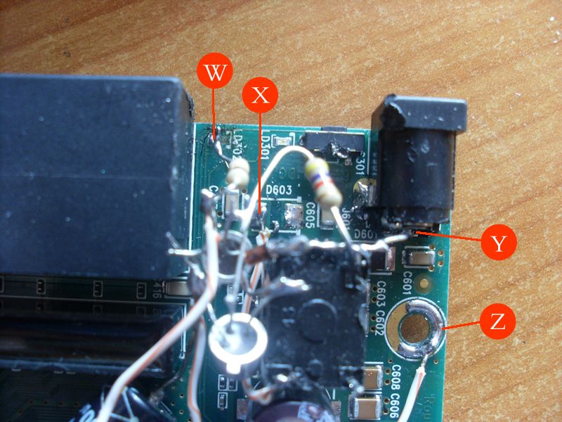
i forgot to say - the ‘Flash Activity’ LED is where the ‘sense’ line comes from, so you should disable anything that does a disk write, like logging. Use Memory or Remote instead.

That looks like some hectic Stuff.


Is that to be able to recive PoE on all ports or does it send Poe over all ports.

If you just solder the wires on, it receives and sends PoE on all Ports.

I did a PCB layout, and there’s a bloke in Romania (i think) making a PCB so you can forget the wires and just solder a small PCB on.

‘hectic’ ? Have you been a WISP for long :wink:

I forgot to say - if you do the wires (or solder on the PCB when it somes) then it receives and sends PoE on all/any port.

Now, how do we add remote reboot to this?

That’s option #4

If you reboot the RB750, then the PoE is disconnected from all 5 ports for about 4 seconds.

Nice hack!

Is the RB750 the only board this can be done to…how about a 433 board?

Clever! Can you add hw watchdog to the mix?

Very nice. If an RB has an extra ethernet port and ethernet status LEDs, and this model of RB lets you turn ports on and off, you could use an ethernet port’s status LED to power up/power down something with your circuit. Put a loopback plug into the ethernet port (transmit connected to receive), and ethernet would be up whenever the ethernet port is active. (Don’t bridge this port into the rest of the network!) Temporarily disable the ethernet port to turn off the relay controlled poe.

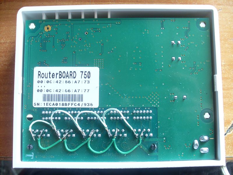
I just found out that the ‘Running’ status of the MT ports can be spoofed by looping back the wires in the RJ45 connector.

One application i thought of for this is to loop back pins 1+3, and have pins 2+6 connected thru a mains-powered relay.

Them when the mains power goes off or back on, you can detect the fact by looking at the port status, and send yourself an email etc.

'course you need battery backup on the AP to be able to do that.

Below is a script (run from Scheduler once in a while) to do that (tested on 3.29).

You just set the ‘port=x’ to select which port you’re montoring, and it uses the Comment field for the port to count how many times it sent you an email - you don’t want it bothing you all the time. ‘emails 2’ means it will send you 2 emails about the power going off/on.

:global port 1
:global emails 2
:global to “adrian@adrianatkins.com
:global server “a.working.smtp.server.com
:global goodtxt “Power OK”
:global badtxt “Power Has Failed”
:global stat
:global ostat
:global cnt

:global goodbody ([/system identity get name]." “.$goodtxt)
:global badbody ([/system identity get name].” ".$badtxt)

:set stat [/interface ethernet find running name=“ether”.$port]
:set ostat [/interface ethernet get (“ether”.$port) comment]
:set cnt [:pick $ostat 0 1]
:set ostat [:pick $ostat 2 100]

:if ( [:typeof $ostat] = “nil” ) do={:set ostat “unknown”}

:if ( $stat = “*”.$port ) do={
:if ( $ostat != $goodtxt ) do={ :set cnt 0 };
:if ( $cnt < $emails ) do={
:set cnt ($cnt + 1);
:log warning ($goodtxt);
/interface ethernet set (“ether”.$port) comment=($cnt." “.$goodtxt)
/tool e-mail send to=$to subject=$goodbody body=$goodbody server=$server
}
} else={
:if ( $ostat != $badtxt ) do={ :set cnt 0 };
:if ( $cnt < $emails ) do={
:set cnt ($cnt + 1);
:log warning ($badtxt);
/interface ethernet set (“ether”.$port) comment=($cnt.” ".$badtxt)
/tool e-mail send to=$to subject=$badbody body=$badbody server=$server
}
}

I’ve just tried it on a 493 board and it works, but the pinning/wiring is different, which is probably the same for any RB that uses the ethernet socket marked as 47F-1205BGYDNW2NL.

If you have your 493 board upside-down, with the PoE and serial sockets facing you, then looking at the pins under the PoE socket, the +ve is on the bottom row, 2nd pin in from the left, and the -ve is on the top row, 3rd in from the left.

I just connected those two pins to the same pins on the next nearest ethernet socket and got an RB333 to power up on PoE from it :slight_smile:

On the RB433,

it has one PoE port?

if you plug power into the RB433 via teh dc jack wil there be PoE (out) on the PoE ethernet port?

So i could connect a second Routerboard to the RB433 with one power supply, and they would be bridged then?

RB433 has 3 Ethernet.

They will only be bridged if you bridge them. Easy in ROS.

It could have PoE on all ports with the instructions i posted for the 493, but you still have to make the bridge in the firmware.

I have not tested that mod on a 433.

If you make this with a 493, and you connect a laptop on it, it’s possible to have problems with the POE and the lan of the laptop. Due to the laptop don’t accept “powered pins”, true?

I think there is a diode to prevent this. But you could remove the diode, at your own risk.

oh ok,

thought maybe could change it in the software.

and with all that wireing at the top?

why are there resisters?

The wiring on the Top is for the circuit that makes the PoE going Out of the port go off for 4 seconds when you reboot the RB750.

The resistors are part of that circuit.

(see the schematic at the top).

That is true.

Some devices do not like PoE at all.

My laptop (acer) is OK with it.