The announced CRS is to be the first real switch from Mikrotik. Unfortunately RouterOS switching support is very limited at the moment.
On select models with specific switch chips (mostly Atheros 8327 and 8316), VLAN Trunking and VLAN Access Ports are supported.
The most glaring omission is any sort of spanning tree support for switching - spanning tree is only supported for bridges, if poorly - only stp and rstp are supported, no mst or pvst / rapid-pvst.
Also, no port channels or any of the other nice features we have come to expect from managed switches, even if it’s the low cost stuff from netgear.
That raises some questions:
Is CRS with the present software support useable for the enterprise scenarios we have become used to using routerboards for?
Is extended switching support planned for future RouterOS releases?
Was CRS delayed because of this - can we hope for better switching support with the CRS release?
So, just to add some info here. PVST is Cisco proprietary. Other vendors (Juniper) do it also (they call it Virtual Spanning Tree or VSTP) but they have to license that crap out. Not sure Mikrotik wants to do that. I don’t blame em either. You shouldn’t expect PVST. I can understand expecting MST though. Even then though, who REALLY uses RSTP in large networks. Not really anyone (if they have sense in actually designing a scalable network). For what it’s worth, it’s NOT worth having layer 2 be anything past the access layer…and even then I personally recommend going layer 3 right down to the access layer.
From what I’ve seen so far…if I remember right…the RouterOS supports port channels/LAGs/LACP bundles/port aggregation here.
Ok, the first question here, is CRS a router or a switch?
In my opinion, it’s a switch, the CPU is much too weak for so many ports. And I do mean switch here, not bridge. That means the usage scenario is datacenter or access layer and it means primarily L2 through the hardware switching functionality.
In routeros as we know it, switching doesn’t support ANY spanning tree. Even proper VLAN support was only added in ROS 6. If it’s a switch, I expect it to be usable as one, and the way it stands now, it probably isn’t.
So the question stands, what are the new switching features added to ROS for CRS.
Which leads me to believe nothing has changed at all. The VLAN functionality is still just as convultued as ever. I was hoping to be able to replace some small Cisco L3 switches with the CRS, but it doesn’t look like that is going to happen. I need multiple L3 VLAN interfaces, and I need to easily be able to configure them as either tagged (trunk) or untagged (access) on any given switch interface.
Currently we are still adding Switching features for the CRS. Right now you get only basic Switch functionality, but the hardware allows for much more, and new features will be added with every software update.
Please give us examples of the most important switch functions that you want us to make.
If you want to do heavy routing (more than several-hundreds of mbit/s) it is not enough. For management tasks and light routing tasks it is more than enough.
If you want wirespeed layer 3 switching/routing you should consider a CCR.
The examples look great on the examples page (along with some Winbox screens to implement them please)
Some setups I would like to see:
Trunk Ports with optional “Native” VLAN (drop down box to select native from all defined VLANS
Allow us a “VLAN’s” section of the cli / Winbox where we define VLANs for the switch
something like / switch vlans add name=“VLAN Name” vlan-id=1234 S-VLAN=yes/no
Use the VLAN’s defined to then add to a trunk port with the VLAN’ on it like we add channel scan into wireless
Allow VLAN Groups like frequency scan groups to easily make regular trunks for deployment (like we have 3 VLANS we deploy on most ports)
These are just my very first ideas. mostly making the system much more simple to deploy them onto the ports.
Being huge fan of MT i get almost every MT new product to check it out and to play around. This time i got CSR125 ros6.5, and boy…
after spending 5hours trying to acomplish the most generic switching tasks i felt stupid as faq because i failed:
didnt find an easy way to assign vlan to a port or easly configure a trunk link and permit all vlans. The way from examples(to match default VID with a “In.Vlan Tran” rule and to apply a different VID) feels complicated. Couldnt get “VLAN” and “VLAN Tagging” tabs to work at all
didnt find a way to terminate vlan on a switch(SVI)
unclear with STP configuration beeing only for bridge interfaces
Lack of documentation on switching functions
Putting my new CSR125 on a shelf for some time, unusable…
MT’s VLAN configuration has always been overly-complicated and confusing. An example of what the CRS should be able to do (using Cisco):
interface vlan10
ip address 10.1.1.1/24
!
interface vlan20
ip address 10.2.1.1/24
!
interface gigabitethernet0/1
desc trunk to another switch (tagged)
switchport mode trunk
switchport trunk allowed vlan 10,20
!
interface gigabitethernet0/2
desc uplink to PC (untagged)
switchport
switchport mode access
switchport access vlan 10
!
So, we create two L3 VLAN’s and assign IP addresses to them (an “SVI” in Cisco). This enables routing between the two VLANs. Next, we turn Port1 into a dot1q trunk port which tags both VL10 and VL20. Port 2 is an access port (untagged). In this configuration, I can easily assign VL10 or VL20 to any switchport on the switch, tagged or untagged. MT needs to be able to do this, ESPECIALLY on a product that you are calling a “fully capable L3 switch.”’ Otherwise, it’s just another MT router.
Until this functionality exists, I won’t be purchasing any of these, and I won’t recommend them to anyone that is looking for a L3 switch.
While there are plenty of new options I can concur that the interface and configuration still seems a bit odd and I haven’t had much luck getting the example configs working.
For starters the example listings for port based vlan (what I’m interested in) are incorrect on the wiki:
/interface ethernet switch ingress-vlan-translation
add switch=switch1 port=ether6 customer-vid=0 new-customer-vid=200Should be:
/interface ethernet switch ingress-vlan-translation
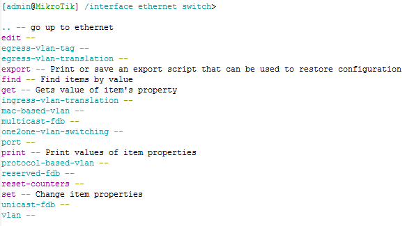
add switch=switch1 port=ether6 match-customer-vid=0 new-customer-vid=200Here’s the listing from the switch itself of some of the new options:
Along with this it’s not really clear how pulling things back to vlan 0 is support to work for configs.
IE:
If I want tagged/trunked vlans 20,30,40 coming in on ether1 and
vlan 20 untagged out ether2
vlan 30 untagged out ether3
vlan 40 untagged out ether4
I would assume I should:
accept tagged vlans 20,30,40 on ether1
ensure traffic in ether2,ether3,ether4 is tagged as it comes in with the respective vlan (20,30,40)
ensure traffic passing out ether2,ether3,ether4 is untagged as it passes out with the respective vlan (20,30,40)
But this does not align with how I configure the ports.
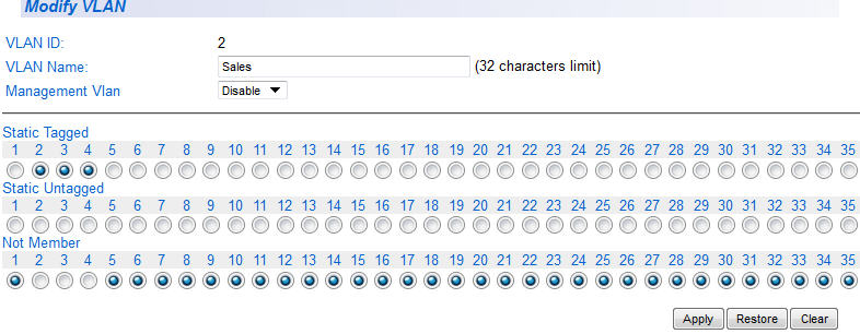
Perhaps a graphical configuration model for ease of setup which would then allow us to export configs and see what they’re supposed to look like?
IE:
or
U = Untagged
T = Tagged
X = Not included in vlan group
Along with these options:
DHCP Snooping,
Multicast and Unicast traffic filtering,
port-based mac-address limiting (with a recovery timeout of some sort)
the switch based ACL/firewall options also appear to have gone from the switch config page on the CRS too
Also, if it’s a Layer3 switch, we really need to [easily] be able to terminate L3 VLAN’s (SVI) on the switch it’s self.
ie, create a VLAN interface, assign an IP address to it, then be able to assign that VLAN to multiple physical interfaces (tagged or untagged). This would also enable routing between VLANs.
The features that Omega said are most definitely needed, but those are typically found in any off-the-shelf managed L2 switch.
Is it possible on the cloud router switch to perform bonding/link aggregation/teaming using protocols such as 802.3ad (LACP). I know it is possible to perform the bond using the routerOS functions however that requires a CPU based bond. is it possible to perform the bond with the layer 3 switch chip for wire speed channel bonding? I would like to use the switching hardware because the CPU generally maxes out prior to 1Gb/s throughput thus bonding is actually slowing the network down. Also managed switches from most other vendors support this functionality.
I was wondering if there are plans for a “Multiple SFP” CRS switch soon. F.ex. 24 Gig SFP ports (and maybe 4-8 gig etherports, preferably without combo share with SFP ports. But if only possibility with combo for etherports).
An “all” SFP switch is very useful in central points of Optical networks and in distributionpoints of f.ex. FTH.
Could we be seeing such a product in near future?
Also it could be nice with atleast 2 SFP ports on normal CRS switch, so it is possible to have both an inlink AND an outlink on optical SFP port.