
Hi!
I've recently started playing around with VPNv4 and VRFs on Mikrotik by configuring some P, PE and CPE routers.
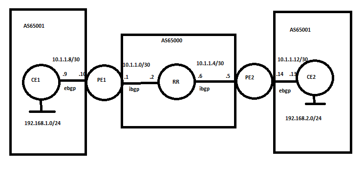
This is how my setup looks like
I've configured the following
- OSPF as IGP in the MPLS core (P1, P2, PE1 and PE2)
- MPLS on all interfaces not facing customers (P1, P2, PE1 and PE2)
- P1 as BGP route reflector with VPNv4 address family, which is then peering with PE1 and PE2
- VRF on PE1 and PE2 interfaces facing the customer (RD 1:1, import 1:1 export 1:1)
- OSPF on the VRF interfaces which redistributes BGP routes (VPNv4)
- OSPF on CPE1-1 and CPE1-2
I can see the routes showing up on each CPE and they can ping each others internal network (192.168.10.1 and 192.168.20.1). At first when I did a traceroute between CPE1-1 and CPE1-2 the first 4 jumps failed, and on the 5th it arrived (propaget TTL is enabled).
[admin@CPE1-1] > tool trace 192.168.20.1
# ADDRESS LOSS SENT LAST AVG BEST WORST STD-DEV STATUS
1 100% 6 timeout
2 100% 6 timeout
3 100% 6 timeout
4 100% 5 timeout
5 192.168.20.1 0% 5 8.8ms 7 3.8 8.8 1.9
It took me a while to figure it out, that the customer facing networks on PE1 and PE2 (10.12.0.0/24 and 10.56.0.0/24) were not in the main routing table, they were in the VRFs routing table, and because of this the lookup failed on both PE routers. I added a static route for the networks on each PE in their main routing table and now I can see the PE routers in the traceroute.
[admin@CPE1-1] > tool trace 192.168.20.1
# ADDRESS LOSS SENT LAST AVG BEST WORST STD-DEV STATUS
1 10.12.0.2 0% 2 3ms 2.1 1.2 3 0.9
2 100% 2 timeout
3 100% 1 timeout
4 10.45.0.5 0% 1 7.3ms 7.3 7.3 7.3 0
5 192.168.20.1 0% 1 10.6ms 10.6 10.6 10.6 0
Is it correct to add static routes like this?
As you can see there are 2 jumps that fails. I guess it's where it's going through my MPLS core? Why do they fail, and why wont the customer see the MPLS labels?
If I do a traceroute again, but with porpagate TTL disabled these 2 jumps disaperes as show below
[admin@CPE1-1] > tool trace 192.168.20.1
# ADDRESS LOSS SENT LAST AVG BEST WORST STD-DEV STATUS
1 10.12.0.2 0% 3 1ms 1.3 1 1.6 0.2
2 10.45.0.5 0% 3 3.9ms 4.1 3.9 4.2 0.1
3 192.168.20.1 0% 3 6.3ms 6.7 5.7 8.2 1.1
If I do a traceroute from PE1 to PE2 (both to the loopback and far end interface, and propagate TTL enabled again) I can see the MPLS labels
[admin@PE1] > tool traceroute 5.5.5.5
# ADDRESS LOSS SENT LAST AVG BEST WORST STD-DEV STATUS
1 10.23.0.3 0% 4 2.6ms 4.4 2.6 6.4 1.5 <MPLS:L=47,E=0>
2 10.34.0.4 0% 4 2.9ms 3.9 2.9 4.7 0.8 <MPLS:L=40,E=0>
3 5.5.5.5 0% 4 2.4ms 4.3 2.4 7.2 2
[admin@PE1] > tool traceroute 10.56.0.5
# ADDRESS LOSS SENT LAST AVG BEST WORST STD-DEV STATUS
1 10.23.0.3 0% 4 2.8ms 3 2.8 3.2 0.2 <MPLS:L=52,E=0>
2 10.34.0.4 0% 4 2.9ms 2.8 2.4 3.3 0.4 <MPLS:L=44,E=0>
3 10.56.0.5 0% 4 2.5ms 2.7 2.5 2.9 0.2
So again, why wont the customer see the MPLS labels?
MPLS BGP VPNv4 with OSPF as PE-CPE
You do not have the required permissions to view the files attached to this post.
-

-
unixlamaster
just joined
- Posts: 2
- Joined:
Re: MPLS BGP VPNv4 with OSPF as PE-CPE
Hi
I also have a question
Collected by a manual scheme http://wiki.mikrotik.com/wiki/Manual:La ... PN_example
file result and configs attached.
I add a line:
/mpls set propagate-ttl = no
But this does not work!!!
PC2> trace 10.1.1.1
trace to 10.1.1.1, 8 hops max, press Ctrl + C to stop
1 * * *
2 * * *
3 * 10.1.1.1 5.976 ms (ICMP type: three, code: 3, Destination port unreachable)
How to be?
How to build a transport MPLS network that it would not be seen in the trace?
You do not have the required permissions to view the files attached to this post.
-

-
shaoranrch
Member Candidate

- Posts: 184
- Joined:
Re: MPLS BGP VPNv4 with OSPF as PE-CPE
Hello,[admin@CPE1-1] > tool trace 192.168.20.1
# ADDRESS LOSS SENT LAST AVG BEST WORST STD-DEV STATUS
1 10.12.0.2 0% 2 3ms 2.1 1.2 3 0.9
2 100% 2 timeout
3 100% 1 timeout
4 10.45.0.5 0% 1 7.3ms 7.3 7.3 7.3 0
5 192.168.20.1 0% 1 10.6ms 10.6 10.6 10.6 0
Is it correct to add static routes like this?
No, it's not. there's a reason for this, VRF routes are supposed to be kept within their own table, only PE (on corresponding VRF table) and CE (on main table) routers need to know about said routes, P routers don't need to know about them. This allows you to have overlaping prefixes within customers and avoid having your core network flooded with hundred or even thousands of routes, also think about it, what's the point on doing this? now think about how would this scale if you needed to add an static route for every route on your VRF tables, and what would happen if VRF A (Customer A) uses 192.168.0.0/24 and then VRF B (Customer B) also uses 192.168.0.0/24, how do you think traffic would get routed?
L3VPN uses MPLS with a stack of 2 labels, one outer label for transportation within the MPLS cloud and one inner label that identifies the VPN who "owns" this traffic, this last label is only understandable by PE routers and it allows them to know what routing table (VRF table) they should look into in order to properly forward the traffic.
Re: MPLS BGP VPNv4 with OSPF as PE-CPE
Ok, I get that.
I removed the static routes again. But I dont understand why I get some hops that fails, like the first four hops here when I do a trace from CPE1-1 to CPE1-2 on the other end. I followed this guide http://www.tech-blog.info/wp/?p=104 where it shows I should get response but from 0.0.0.0 at least.
[admin@CPE1-1] > tool traceroute 10.56.0.6
# ADDRESS LOSS SENT LAST AVG BEST WORST STD-DEV STATUS
1 100% 3 timeout
2 100% 2 timeout
3 100% 2 timeout
4 100% 2 timeout
5 10.56.0.6 0% 2 4.9ms 10.1 4.9 15.3 5.2
When I disable "propagate ttl" I get this
[admin@CPE1-1] > tool traceroute 10.56.0.6
# ADDRESS LOSS SENT LAST AVG BEST WORST STD-DEV STATUS
1 100% 3 timeout
2 100% 3 timeout
3 10.56.0.6 0% 3 7ms 6.5 6 7 0.5
Any idea why?
Re: MPLS BGP VPNv4 with OSPF as PE-CPE
Why use a route reflector? Just set up iBGP between PE1 and PE2. There's no need to run BGP on P routers with MPLS enabled.
Don't forget that a LSP is one way. For the TTL to expire, the packet first has to reach the egress of the LSP. Think about it, if P1 needs to send an ICMP time exceeded message to the originator, it needs a route to that originator. It doesn't have one, so it has to send it forward along the path.
http://www.ciscopress.com/articles/arti ... 4&seqNum=4
Surely you don't want the customer to see your internal infrastructure?why wont the customer see the MPLS labels?
Don't forget that a LSP is one way. For the TTL to expire, the packet first has to reach the egress of the LSP. Think about it, if P1 needs to send an ICMP time exceeded message to the originator, it needs a route to that originator. It doesn't have one, so it has to send it forward along the path.
http://www.ciscopress.com/articles/arti ... 4&seqNum=4
Re: MPLS BGP VPNv4 with OSPF as PE-CPE
I've just seen another thread saying RouterOS does not support label distribution via BGP. I suspect this could be the problem - P2 does not have VPN label knowledge, so when the TTL expires inside the MPLS core, P2 forwards each ICMP time exceeded message without a VPN label. With no VPN label, the return path is now using the global routing table, and consequently doesn't have a route back to the source. With normal traffic (no TTL exceeded) P2 simply pops the top label, leaving the VPN label intact.
Try adding BGP to P2 so that the VPN labels can be exchanged with LDP.
Try adding BGP to P2 so that the VPN labels can be exchanged with LDP.
Re: MPLS BGP VPNv4 with OSPF as PE-CPE
You are right, I don't want to expose my core network to the customer. I hide this when I disable the setting "propagate TTL" in MPLS, but for now I want to expose it so I can troubleshoot. I got this to work with core MPLS, but not from a customer VPNv4-route.
I want a route reflector as I want to scale out with more routers as the network expands.
I added a BGP to P2 as well, but that didn't change anything. When I "hide" the core network I still get two hops that fails in my traceroute before the customer reach the other end. I can't really see why that is happening.
Re: MPLS BGP VPNv4 with OSPF as PE-CPE
When the TTL expires on either of the P routers, they have to build an ICMP reply to the source host. Unless the two P routers also have the customer VRF and routes, there is no way for them to build the ICMP messages back to the source. That, of course, defeats the object of running MPLS. The ICMP packet should be sent along the original path with VPN label intact, but I suspect this is not happening, since when using the global routing table the MPLS labels are displayed just fine.
Try running a packet capture on the egress path to see what is actually contained in the ICMP time exceeded packet. If you're not seeing the inner VPN label it would explain why the traceroute fails.
Try running a packet capture on the egress path to see what is actually contained in the ICMP time exceeded packet. If you're not seeing the inner VPN label it would explain why the traceroute fails.
Re: MPLS BGP VPNv4 with OSPF as PE-CPE
Where do you mean by the egress path? If I trace from CPE1-1 to CPE1-2 and do a packet capture on PE2?Try running a packet capture on the egress path to see what is actually contained in the ICMP time exceeded packet. If you're not seeing the inner VPN label it would explain why the traceroute fails.
Re: MPLS BGP VPNv4 with OSPF as PE-CPE
Yes, on e0 on PE2 - this would be the point P2 removes the outer label, so you should still see the vpn label. If there's no label here at all, it explains why the traceroute times out at P1 and P2. Remember you're looking for the ICMP time exceeded packets originating from P1 and P2.
Re: MPLS BGP VPNv4 with OSPF as PE-CPE
I'm running a trace from CPE1-1 to CPE1-2, and a packet sniffer active on PE2 interface e0 but it looks odd.
I don't know if there is something wrong with my packet sniffing or if it can't capture correctly inside GNS3. I'm running this as a lab inside GNS3 with packet sniffer enabled and streaming it to my physical computer (192.168.154.1) where I'm running Wireshark.
See attachment, and take notice of the ICMP packets between 192.168.154.1 (Wireshark computer) and 192.168.154.5 (PE2). They are not all just ICMP, but has LDP, OSPF and other stuff inside. I guess this happens when you capture and stream to a Wireshark server like this?
You do not have the required permissions to view the files attached to this post.
Re: MPLS BGP VPNv4 with OSPF as PE-CPE
Something isn't right there. It's normal to see the packet data in ICMP unreachable messages that generated it, but I can only see control plane packets, not data plane (the ping from CE1 to CE2).


Re: MPLS BGP VPNv4 with OSPF as PE-CPE
Insert a switch between two Mikrotiks so you can capture directly in Wireshark.
Re: MPLS BGP VPNv4 with OSPF as PE-CPE
I bought some small RB750 and setup the same topology and did a new trace. This time I actually capture some ICMP packets (see attachment), but I still get 2 jumps that fails with Propagate TTL disabled.
[admin@CPE1] > tool traceroute 10.56.0.6
# ADDRESS LOSS SENT LAST AVG BEST WORST
1 100% 211 timeout
2 100% 211 timeout
3 10.56.0.6 0% 210 0.5ms 0.5 0.4 0.9
[admin@CPE1] > tool traceroute 10.56.0.6
# ADDRESS LOSS SENT LAST AVG BEST WORST
1 100% 211 timeout
2 100% 211 timeout
3 10.56.0.6 0% 210 0.5ms 0.5 0.4 0.9
You do not have the required permissions to view the files attached to this post.
Re: MPLS BGP VPNv4 with OSPF as PE-CPE
Ok, now I did a new packet sniffer on all routers and all interfaces, and I can now see the right MPLS tags (both inner and outer) all the way between CPE1 and CPE2. So it all looks ok there.
Hi Sir lillis,
Did you already resolve your issue? im also experiencing this one.
Re: MPLS BGP VPNv4 with OSPF as PE-CPE
Hi guys, anyone already resolve this issue? ive tried searching for this kind of issue, but i dont see any other vendor experiencing this kind of issue. please help


Re: MPLS BGP VPNv4 with OSPF as PE-CPE
I'm afraid I can't assist but I'm having the same issue.
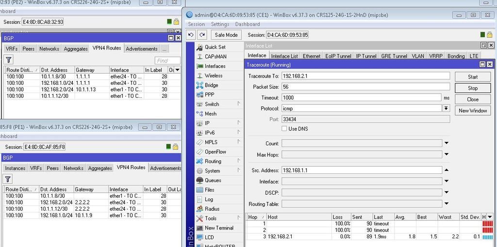
I've mirrored the configuration shown on the Wiki, which is also very similar to this Blog post. Both clearly show the PE routers responding in a traceroute, however I only see the final destination respond-
I believe this is because the ICMP TTL exceeded responses are using the main routing table, so they have no route to the source of the traceroute., however this worked in the examples linked above. Can anyone tell me what I'm doing wrong?
Topology

Router A
Router B
Router C
Router D
Router E
I've mirrored the configuration shown on the Wiki, which is also very similar to this Blog post. Both clearly show the PE routers responding in a traceroute, however I only see the final destination respond-
Code: Select all
[admin@RouterA] > / tool traceroute  10.7.7.5
 # ADDRESS                          LOSS SENT    LAST     AVG    BEST   WORST
 1                                  100%    3 timeout
 2                                  100%    2 timeout
 3 10.7.7.5                           0%    2  12.6ms    15.4    12.6    18.2
Topology
Router A
Code: Select all
/ip address
add address=10.1.1.1/24 interface=ether1 network=10.1.1.0
/routing ospf network
add area=backbone network=10.1.1.0/24
/system identity
Code: Select all
/interface bridge add name=lobridge
/routing ospf instance
set [ find default=yes ] redistribute-bgp=as-type-1 routing-table=vrf1
/ip address
add address=10.1.1.2/24 interface=ether2 network=10.1.1.0
add address=10.2.2.2/24 interface=ether3 network=10.2.2.0
add address=10.9.9.2 interface=lobridge network=10.9.9.2
/ip firewall mangle
add chain=input in-interface=ether2
/ip route
add distance=1 dst-address=10.9.9.3/32 gateway=10.2.2.3
add distance=1 dst-address=10.9.9.4/32 gateway=10.2.2.3
/ip route vrf
add export-route-targets=10.1.1.1:111 import-route-targets=10.1.1.1:111 \
    interfaces=ether2 route-distinguisher=10.1.1.1:111 routing-mark=vrf1
/mpls
set propagate-ttl=no
/mpls ldp
set enabled=yes transport-address=10.9.9.2
/mpls ldp interface
add interface=ether3
/routing bgp instance vrf
add redistribute-connected=yes redistribute-ospf=yes routing-mark=vrf1
/routing bgp peer
add address-families=vpnv4 name=peer1 remote-address=10.9.9.3 remote-as=65530 \
    update-source=lobridge
/routing ospf network
add area=backbone network=10.1.1.0/24
/system identity
set name=RouterB
Code: Select all
/interface bridge add name=lobridge
/ip address
add address=10.2.2.3/24 interface=ether3 network=10.2.2.0
add address=10.3.3.3/24 interface=ether2 network=10.3.3.0
add address=10.9.9.3 interface=lobridge network=10.9.9.3
/ip route
add distance=1 dst-address=10.9.9.2/32 gateway=10.2.2.2
add distance=1 dst-address=10.9.9.4/32 gateway=10.3.3.4
/mpls
set propagate-ttl=no
/mpls ldp
set enabled=yes transport-address=10.9.9.3
/mpls ldp interface
add interface=ether2
add interface=ether3
/routing bgp instance vrf
add redistribute-connected=yes redistribute-ospf=yes routing-mark=vrf1
/routing bgp peer
add address-families=vpnv4 name=peer1 remote-address=10.9.9.2 remote-as=65530 \
    route-reflect=yes update-source=lobridge
add address-families=vpnv4 name=peer2 remote-address=10.9.9.4 remote-as=65530 \
    route-reflect=yes update-source=lobridge
/system identity
Code: Select all
/interface bridge
add name=lobridge
/routing ospf instance
set [ find default=yes ] redistribute-bgp=as-type-1 routing-table=vrf1
/ip address
add address=10.3.3.4/24 interface=ether2 network=10.3.3.0
add address=10.4.4.4/24 interface=ether3 network=10.4.4.0
add address=10.9.9.4 interface=lobridge network=10.9.9.4
/ip route
add distance=1 dst-address=10.9.9.2/32 gateway=10.3.3.3
add distance=1 dst-address=10.9.9.3/32 gateway=10.3.3.3
/ip route vrf
add export-route-targets=10.1.1.1:111 import-route-targets=10.1.1.1:111 \
    interfaces=ether3 route-distinguisher=10.1.1.1:111 routing-mark=vrf1
/mpls
set propagate-ttl=no
/mpls ldp
set enabled=yes transport-address=10.9.9.4
/mpls ldp interface
add interface=ether2
/routing bgp instance vrf
add redistribute-connected=yes redistribute-ospf=yes routing-mark=vrf1
/routing bgp peer
add address-families=vpnv4 name=peer1 remote-address=10.9.9.3 remote-as=65530 \
    update-source=lobridge
/routing ospf network
add area=backbone network=10.4.4.0/24
/system identity
set name=RouterD
Code: Select all
/ip address
add address=10.4.4.5/24 interface=ether1 network=10.4.4.0
add address=10.7.7.5/24 interface=ether2 network=10.7.7.0
/routing ospf network
add area=backbone network=10.4.4.0/24
add area=backbone network=10.7.7.0/24
/system identity
set name=RouterE
Re: MPLS BGP VPNv4 with OSPF as PE-CPE
The response I eventually got from a Mikrotik trainer was that this might have been introduced in newer firmware versions. In all examples I've found they have been running very old firmware, but I haven't confirmed this myself.
Who is online
Users browsing this forum: No registered users and 21 guests