Page 1 of 1
New Packet flow diagram
Posted: Fri May 17, 2013 1:21 pm
by normis
We have a new concept for the packet flow diagram, applying to RouterOS v6. Please make suggestions for more example drawings, or other comments.
UPDATED
PacketFlowDiagram_v6_page1.jpg
PacketFlowDiagram_v6_page2.jpg
PacketFlowDiagram_v6_page3.jpg
PacketFlowDiagram_v6_example1.2.jpg
PacketFlowDiagram_v6_example2.1.jpg
PacketFlowDiagram_v6_example3.1.jpg
Re: New Packet flow diagram
Posted: Fri May 17, 2013 7:08 pm
by cheeze
I think they're great

However, I don't know what the letters/numbers mean.
Otherwise, awesome.
Re: New Packet flow diagram
Posted: Fri May 17, 2013 9:12 pm
by rkau045
The letters in the circles are jumps. So, for example, the output from mpls chart at H goes back into the main loop at H.
Sent from my XT912 using Tapatalk 2
Re: New Packet flow diagram
Posted: Fri May 17, 2013 10:51 pm
by blingblouw
please please please can we do something before hotspot in, maybe like pre-hotspot-in or move it after mangel pre-routing so that we don't have to count all traffic in a hotspot users sessions.
I really need to allow some sites not to be accounted for in a hotspot session!
Re: New Packet flow diagram
Posted: Mon May 20, 2013 8:22 am
by normis
I think they're great
However, I don't know what the letters/numbers mean.
Otherwise, awesome.
letters are transition points from the first main diagram to more detailed ones. This way we reduced amount of information in main diagram
numbers are used to show packet path through router
Re: New Packet flow diagram
Posted: Mon May 20, 2013 1:05 pm
by nz_monkey
The new diagram is really good.
It is clearer than the previous diagram.
Re: New Packet flow diagram
Posted: Mon May 20, 2013 8:08 pm
by JJCinAZ
Like the new diagrams. One suggestion is to add detail on the "Use MPLS?" and "Use Route?". If you compare these decisions in the flow chart to the first decision after physical input, "In-Interface Bridge Port?", it seems to me that the first decision is much more self describing than the others -- "Is the in-interface in a bridge?" vs. "Are we going to use MPLS?" If it was more clear as to the logic for "Use MPLS" or "Use Route", then it might be more useful in learning RouterOS.
Re: New Packet flow diagram
Posted: Tue May 21, 2013 6:27 am
by gregsowell
Looks clean guys. Nice work.
Re: New Packet flow diagram
Posted: Tue May 21, 2013 10:33 am
by normis
Thanks for the suggestions. First post has been updated with new images. Please make more suggestions, what more examples would you need in the manual?
Re: New Packet flow diagram
Posted: Tue May 21, 2013 11:24 am
by andriys
Not quite clear where the entrance/exit points are. In my opinion, it would be better if physical interface nodes were visually "open" (not frame-bounded to each other).
Re: New Packet flow diagram
Posted: Tue May 21, 2013 11:25 am
by normis
Not quite clear where the entrance/exit points are. In my opinion, it would be better if physical interface nodes were visually "open" (not frame-bounded to each other).
they are indicated by green/red color
Re: New Packet flow diagram
Posted: Tue May 21, 2013 12:05 pm
by ener
very nice. maybe soon i could understand hope so
Re: New Packet flow diagram
Posted: Thu Jun 13, 2013 8:36 am
by omidkosari
Very nice but unfortunately still no place for old feature request
Umetered Content for PPP http://forum.mikrotik.com/viewtopic.php ... 50#p235456
Re: New Packet flow diagram
Posted: Mon Jun 17, 2013 11:04 pm
by majkel
When it will be use in 6.x ?

Re: New Packet flow diagram
Posted: Tue Jun 18, 2013 10:24 am
by Chupaka
When it will be use in 6.x ?
it IS, just like the previous one. it's just a look from another point. like a map VS globe - the Earth is still the same
Re: New Packet flow diagram
Posted: Wed Jun 26, 2013 8:44 am
by mknnoc
I am not sure if I understand it correctly. If possible, can you write some explanation under each packet flow diagram?
Re: New Packet flow diagram
Posted: Wed Jun 26, 2013 9:26 am
by normis
I am not sure if I understand it correctly. If possible, can you write some explanation under each packet flow diagram?
traffic goes into the "green" physical interface. then follow the arrows and answer questions.
Re: New Packet flow diagram
Posted: Wed Jun 26, 2013 1:49 pm
by tomaskir
How do trunks (LACP) come into this?
Or are they "transparent" as far as the packet flow diagram is concerned?
Re: New Packet flow diagram
Posted: Wed Aug 14, 2013 10:46 pm
by ekkas
Please help me understand as I'm obviously missing something here...
In ROS 5 you could double-QoS by:
1)Mangle in prerouting, prioritise in Global-In HTB (all in prerouting sub-section)
2)Mark in forward/postrouting, shape in Interface HTB
Now in ROS 6 the global HTB resides in the Input chain, not the prerouting chain!?
So how do I achieve double-QoS with ROS6 then?
Regards
Ekkas
Re: New Packet flow diagram
Posted: Thu Aug 15, 2013 12:32 am
by Chupaka
in v6:
1) mark in prerouting/forward/postrouting, prioritize in Global HTB in Queue Tree
2) shape in Simple Queues
Re: New Packet flow diagram
Posted: Thu Aug 15, 2013 10:14 am
by ekkas
Thanks for that, but what I do not understand is if the diagram shows Global HTB in Input chain, then it's not supposed to get any forwarding traffic?
According to diagrams:
A) Traffic to Router(v5):
PreRouting (ConnTrack, Mangle, DstNAT, Global HTB)
Input (Mangle, Filter)Traffic to Router(v5):
B)Traffic forwarded(v5):
PreRouting (ConnTrack, Mangle, DstNAT, Global HTB)
Forward (Mangle, Filter)
C)Traffic to Router(v6):
PreRouting (ConnTrack, Mangle, DstNAT)
Input (Mangle, Filter, Global HTB)
D)Traffic forwarded(v6):
PreRouting (ConnTrack, Mangle, DstNAT)
Forward (Mangle, Filter,?)
....
In scenario D, there is no Global HTB in prerouting, according to diagram it is now in Input chain, but Input chain is not used if it is forwarded traffic.
I'm not suggesting ROS is broken, I'm suggesting that possibly the diagram is wrong, or does ROS6 process Input chain for forwarded traffic as well now?
Regards
Ekkas
Re: New Packet flow diagram
Posted: Thu Aug 15, 2013 11:31 am
by andriys
the diagram shows Global HTB in Input chain
It shows it not only in Input chain, but in the Postrouting chain as well.
See above the last two blocks in postrouting.
Re: New Packet flow diagram
Posted: Thu Aug 15, 2013 11:39 am
by ekkas
It shows it not only in Input chain, but in the Postrouting chain as well.
I'm talking about prerouting.
Global has always been in postrouting(before Src-NAT, now after src-NAT), but seems to moved from prerouting to input, that's the point I'm trying to make.
V5:
V6:

Re: New Packet flow diagram
Posted: Thu Aug 15, 2013 1:11 pm
by andriys
Any kind of traffic first hits Global HTB, then Simple Tree, and it does it only once. Input traffic hits them in the Input, while Output and Forward traffic - in the Postrouting. The packet flow has changed and you will need to adopt to it.
Re: New Packet flow diagram
Posted: Thu Aug 15, 2013 2:40 pm
by ekkas
Any kind of traffic first hits Global HTB, then Simple Tree, and it does it only once.
Ok, that makes sense.
The packet flow has changed and you will need to adopt to it.
I need to understand before I can adapt.
Where would you want QueueTree or Simple Queues in Input chain, except for web proxy maybe? Control is outbound?
Anyways...
Let me put it this way...
For normal unbridged, routed traffic a packed would travel roughly.(#=PacketMark *=Queue)
ROS 5
1-)Prerouting
1a)Mangle Prerouting #1
1b)Dst NAT
1c)Global-In Global-Total HTB *1
2-)Forward
2a)Mangle forward #2
2b)Filter forward
3-)PostRouting
3a)Mangle Postrouting #2
3b)Global-Out Global-Total HTB *2
3c)Src-NAT
4-)Interface HTB *2
So here (if I understand it correctly), you could:
new-packet-mark @ ManglePrerouting(1a), then queue @ Global-In/Global-total(1c)
Then re-mark the packet @ MangleForward(2a) or ManglePostrouting(3a), then queue @Global-out(3b) or Interface HTB(4-)
Correct?
ROS 6:
1-)Prerouting
1a)Mangle Prerouting #1
1b)Dst NAT
2-)Forward
2a)Mangle forward
2b)Filter forward
3-)PostRouting
3a)Mangle Postrouting
3b)src-NAT
3c)Global HTB *1?
3d)Simple queues
4-)Interface HTB
Here, the first queue that you reach, is only in Global HTB(3c), after prerouting, forward, postrouting Mangles. There is no mangle opportunity after that to re-mark the packet before Interface HTB(4-)?
I guess my question is then, can a packet carry more than one mark? Otherwise, how does a packet get remarked if the sequence above is correct?
Thanks for your patience
Ekkas
Re: New Packet flow diagram
Posted: Thu Aug 15, 2013 3:40 pm
by Chupaka
There is no mangle opportunity after that to re-mark the packet before Interface HTB(4-)?
no opportunity
can a packet carry more than one mark?
it cannot
Re: New Packet flow diagram
Posted: Thu Aug 15, 2013 5:30 pm
by ekkas
Thanks Chupaka,
it would seem then a big downgrade from ROS5?
How can you do double-control QoS, i.e. shape by client type and QoS by traffic type on one router?
Re: New Packet flow diagram
Posted: Fri Aug 16, 2013 1:17 am
by Chupaka
you may use dynamic Simple Queues for shaping, one queue per user - they are speedy now
Re: New Packet flow diagram
Posted: Fri Aug 16, 2013 3:15 am
by ekkas
That is all fine and well, but the question is how to do it twice.
1)Per user (Throttling)
2)Total outgoing (QoS)
Where to mark and queue it second time?
Regards
Ekkas
Re: New Packet flow diagram
Posted: Fri Aug 16, 2013 9:33 am
by macgaiver
1) mark by traffic type in any mangle chain... - i suggest "forward"
2) prioritize traffic by traffic type in HTB global
3) use simple queues to apply individual user limits (use target as individual IP, or network and PCQ queue type)
Re: New Packet flow diagram
Posted: Mon Sep 02, 2013 2:34 am
by infused
Can anyone chuck this in a nice, printable pdf?
Re: New Packet flow diagram
Posted: Tue Sep 03, 2013 6:39 pm
by Toby7
One addon from my point of view: I would like to have colours in the picture, they make the boxes much more clearer!
PDF is also a good point. Please publish a vector graphics inside the PDF so that we can enjoy a real wallpaper

Thank you!
Re: New Packet flow diagram
Posted: Tue Sep 03, 2013 11:27 pm
by ojsa
Is it possible to get this flow chart pictures in SVG or other vectorbased picture format?
Re: New Packet flow diagram
Posted: Thu Sep 05, 2013 9:33 am
by normis
Is it possible to get this flow chart pictures in SVG or other vectorbased picture format?
The original is in Open Office, so no. You could re-draw it as vector and share
Re: New Packet flow diagram
Posted: Thu Sep 05, 2013 11:43 am
by sergey
Guys
Thank you very much for for the diagram. They are very useful and clear. Well done!
Questions:
1. Could you add they to official documentation (WiKi)?
2. Is it possible to get originals for personal use? I'd want to add comments to the diagrams and print.
Thank you.
Re: New Packet flow diagram
Posted: Wed Sep 25, 2013 4:01 pm
by mrz
Re: New Packet flow diagram
Posted: Wed Sep 25, 2013 5:05 pm
by AlArenal
Great, thx alot!
P.S.:
This would should go into the wiki
Re: New Packet flow diagram
Posted: Wed Sep 25, 2013 5:19 pm
by mrz
It is already there. Images you see here are linked to wiki
Re: New Packet flow diagram
Posted: Thu Sep 26, 2013 9:45 am
by macgaiver
Yes, thanks, finally i can replace my old packet flow diagram printouts that hangs on the wall just across the workplace.
Added PDF that i will use if someone wants to do the same
Re: New Packet flow diagram
Posted: Thu Nov 07, 2013 5:16 pm
by arahim52
Thanks for sharing this post to us. This is really nice information.
[url=http://www.%20marnetllc.com]IT Network Support[/url]
Re: New Packet flow diagram
Posted: Sat Nov 23, 2013 2:30 pm
by HaPe
What is the name of software used to create this diagrams?
Re: Odp: New Packet flow diagram
Posted: Sat Nov 23, 2013 4:17 pm
by ohara
MS Visio
Re: New Packet flow diagram
Posted: Sun Nov 24, 2013 10:33 am
by Chupaka
The original is in Open Office
Re: New Packet flow diagram
Posted: Wed Jan 08, 2014 1:13 pm
by siscom
Hi,
In the wiki the following files seem to be missing from the page titled 'Manual:Packet Flow v6' -
http://wiki.mikrotik.com/index.php?titl ... ples_b.gif
http://wiki.mikrotik.com/index.php?titl ... ples_c.gif
Rgds,
Mark.
Re: New Packet flow diagram
Posted: Thu Jan 23, 2014 7:23 pm
by mleducxit
HI all,
I've read many things on this forum and I've track carefully the packet flow, but one thing are still missing. The physical interface rules. Probably it's on the hardware, but try to figure out how can I bridge 5 interfaces on a CCR-1036 6.7, setup a DHCP Server attached to the bridge and control the HTB using the etherX entry. Refering to the scenario PacketFlowDiagram_v6_example1.2.jpg, I've put somes traces (packet log) following the decisions:
There is my config, it's a vanilla one
/interface bridge
add l2mtu=1590 name=BR_TEST
/ip hotspot user profile
set [ find default=yes ] idle-timeout=none keepalive-timeout=2m mac-cookie-timeout=3d
/interface bridge filter
add action=mark-packet chain=input in-interface=ether1 new-packet-mark=PACKET_ETH1_UPLOAD
add action=mark-packet chain=output new-packet-mark=PACKET_ETH1_DOWNLOAD out-interface=ether1
/interface bridge port
add bridge=BR_TEST interface=ether1
add bridge=BR_TEST interface=ether3
add bridge=BR_TEST interface=ether4
add bridge=BR_TEST interface=ether5
/interface bridge settings
set allow-fast-path=no use-ip-firewall=yes use-ip-firewall-for-pppoe=no use-ip-firewall-for-vlan=yes
/ip address
add address=192.168.88.1/24 comment="default configuration" interface=BR_TEST network=192.168.88.0
/ip dhcp-client
add default-route-distance=0 dhcp-options=hostname,clientid disabled=no interface=ether2
/ip dns
set allow-remote-requests=yes
/ip dns static
add address=192.168.88.1 name=router
/ip firewall filter
add action=log chain=forward log-prefix=FILTER
/ip firewall mangle
add action=log chain=forward log-prefix=PREROUTING
/ip firewall nat
add action=masquerade chain=srcnat
So quickly, I've add a Bridge interface name BR_TEST, with eth1,3,4 and 5, eth2 are my dhcp client into my personal network and I masquerade anything trough this interface.
I've disabled the fast path for the bridge and enabled the IP Firewall options to enter into the ip mangle table and grab somes packets log output, log that I have seen into the LOG window.
I've just realized that the represented interface are the bridge interface BR_TEST and not ether2...

I mean, the traffic are still handled by the physical port, not really, but mabe, the virtual BR_TEST port.
Question #1: It is the chipset who do this?
Always referring the chart, I've add two filter rules into the bridge management and now I can track my interface management.
So I've mark my packets, add it on seperated HTB rules and my download queue dont work...
What I'Ve missing?
Re: New Packet flow diagram
Posted: Fri Jan 31, 2014 12:17 pm
by macgaiver
HI all,
...
So quickly, I've add a Bridge interface name BR_TEST, with eth1,3,4 and 5, eth2 are my dhcp client into my personal network and I masquerade anything trough this interface.
I've disabled the fast path for the bridge and enabled the IP Firewall options to enter into the ip mangle table and grab somes packets log output, log that I have seen into the LOG window.
I've just realized that the represented interface are the bridge interface BR_TEST and not ether2...
I mean, the traffic are still handled by the physical port, not really, but mabe, the virtual BR_TEST port.
Question #1: It is the chipset who do this?
Always referring the chart, I've add two filter rules into the bridge management and now I can track my interface management.
So I've mark my packets, add it on seperated HTB rules and my download queue dont work...
What I'Ve missing?
There are two perspectivs when use-ip-firewall is used.
1) layer-2 perspective - when traffic comes via one bridge port and leaves via other port of the same bridge - in this case in and out interfaces will be physical interfaces that are in the bridges
2) layer-3 perspective - when packet is routed to bridge - in all configuration packet will leave via bridge interface cause routing doesn't know anything about bridge ports. for this traffic out interface will be bridge interface and only bridge forwarding table will know what actual physical port it goes out.
This is done with one single reason - so that enabling use-ip-firewall will not break your layer-3 configuration that you might have.
Re: New Packet flow diagram
Posted: Thu Feb 27, 2014 11:25 am
by andriys
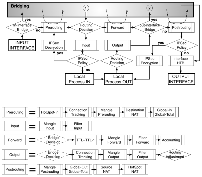
The "IPsec Encryption" and "IPsec Decryption" blocks seem to be mixed up on the Routing diagram.
Re: New Packet flow diagram
Posted: Fri Mar 28, 2014 12:05 am
by noviy
I propose to consider another option
Re: New Packet flow diagram
Posted: Fri Mar 28, 2014 12:16 am
by efaden
I propose to consider another option
I like this.
Sent from my SCH-I545 using Tapatalk
Re: New Packet flow diagram
Posted: Fri Mar 28, 2014 12:53 am
by tomaskir
I propose to consider another option
Great work there!
I like as well - but, is there any way to make it horizontal instad of vertical?
If it was horizontal, it would fit on a widescreen monitor much better.
Also, there is bunch of spelling errors, and on the right side, it should say Encapsulation (currently says Decapsulation).
But great work otherwise!
Could you please please please upload an editable version?
Re: New Packet flow diagram
Posted: Fri Mar 28, 2014 11:14 am
by andriys
I propose to consider another option
Awesome!
What diagramming tool did you use?
Re: New Packet flow diagram
Posted: Fri Mar 28, 2014 12:53 pm
by noviy
Fixed small bug
Re: New Packet flow diagram
Posted: Fri Mar 28, 2014 1:49 pm
by noviy
For preview:
Packet Flow Diagram r20140328.jpg
Re: New Packet flow diagram
Posted: Fri Mar 28, 2014 2:37 pm
by efaden
For preview:
Packet Flow Diagram r20140328.jpg
Nice... PDF or SVG or some sort of vector image would be ideal. Looks great though.
Re: New Packet flow diagram
Posted: Fri Mar 28, 2014 3:25 pm
by noviy
Nice... PDF or SVG or some sort of vector image would be ideal. Looks great though.
See my previous post.
Re: New Packet flow diagram
Posted: Fri Mar 28, 2014 3:42 pm
by tomaskir
Nice... PDF or SVG or some sort of vector image would be ideal. Looks great though.
See my previous post.
Any chance for an editable version?
Thanks!
Re: New Packet flow diagram
Posted: Fri Mar 28, 2014 4:13 pm
by efaden
Nice... PDF or SVG or some sort of vector image would be ideal. Looks great though.
See my previous post.
Any chance for an editable version?
Thanks!
+1
Re: New Packet flow diagram
Posted: Sun Mar 30, 2014 12:31 pm
by noviy
Some changes, for a better understanding of travel of packets.
Fixes:
2014.04.05
- Corrected position 'IPSec Decryption' and 'IPSec Encryption' boxes in ROUTING (gratitude:
macgaiver);
- Fixed form blocks 'Bridge Decision' in 'Forward' and 'Output' Chain.
2014.04.10
- Added "Configurable Facilities": Menu items of RouterOS corresponding function blocks;
- Corrected name of block "Decapsulation
(TE, VPLS, VLAN, Tunnel)" to "Encapsulation (TE, VPLS, VLAN, Tunnel)" in "OUT-INTERFACE
LOGICAL" line;
- Corrected name of block "Bridge Adjustm." to "Routing Adjustm." in "Output" chain (gratitude:
greek);
- Corrected bloks in "Input" and "Postrouting" chains: "Global HTB" > "HTB Global | Queue tree", added "Simple Queues" (gratitude:
greek);
Packet Flow Diagram r20140410.png
P.S. I am also willing to listen to any comments and additions.
Re: New Packet flow diagram
Posted: Fri Apr 04, 2014 2:38 pm
by macgaiver
Nice one - very informative. Just "IPSec Decryption and Encryption boxes need to be swapped - traffic comes to router and in case it is IPSec it will have policy and will be decrypted, not encrypted
and when leaving if there is IPSec policy it will be encrypted - this fix was also done on the wiki:
http://wiki.mikrotik.com/wiki/File:Pack ... m_v6_b.svg
Re: New Packet flow diagram
Posted: Sat Apr 05, 2014 7:21 pm
by noviy
Nice one - very informative. Just "IPSec Decryption and Encryption boxes need to be swapped
Thank you, fixed - see
updated my post.
Re: New Packet flow diagram
Posted: Tue Apr 08, 2014 9:59 pm
by greek
Why last block in output chain is "Bridge Adjustm"?
In original scheme it's "Routing Adj."
And why "Simple queues" blocks is absent in "Input" and "Postrouting" chains ?
Re: New Packet flow diagram
Posted: Thu Apr 10, 2014 2:01 pm
by noviy
Why last block in output chain is "Bridge Adjustm"?
In original scheme it's "Routing Adj."
And why "Simple queues" blocks is absent in "Input" and "Postrouting" chains ?
Fixed - see
updated my post
Thank you!
Re: New Packet flow diagram
Posted: Sat Apr 12, 2014 10:46 am
by normalcy
This is fantastic. Thanks for the effort as I think this layout helps you connect the layers together better than the original separated diagrams. Hopefully it becomes the official one.
Re: New Packet flow diagram
Posted: Mon Apr 14, 2014 12:25 pm
by noviy
To me the first version of diagrams is easier to consume. Second version is a little bit noise. There is too many arrows. Main content is hidden in the web of transitions! Arrows that define logical layers is too big, it's not the main content.
You can download the source in Microsoft Visio 2010 and disable the extra layers, making it easier diagrams at its discretion.
Re: New Packet flow diagram
Posted: Thu Jun 19, 2014 2:33 pm
by normis
noviy, can we use it in the MikroTik Wiki manual ?
Re: New Packet flow diagram
Posted: Fri Jun 20, 2014 12:42 am
by greek
Why first and last figures in output chain are not a parallelepiped as in original scheme?
As i know, parallelepiped has concretic mining in flowchart
http://en.wikipedia.org/wiki/Flowchart
Re: New Packet flow diagram
Posted: Sun Jun 22, 2014 1:56 pm
by noviy
noviy, can we use it in the MikroTik Wiki manual ?
Yes, of course! I'll be glad if it will be useful for Mikrotik project.
Re: New Packet flow diagram
Posted: Fri Jun 27, 2014 11:44 am
by avenn
Excellent thank you for this diagram. I have just got back from a MTCRE course in sunny England and it was causing a positive buzz! Loving it!
Regards
Aidan Venn
Re: New Packet flow diagram
Posted: Sun Jun 29, 2014 7:17 pm
by qwertysqwerty
Excellent work. Very useful indeed!
Thank you.
Re: New Packet flow diagram
Posted: Tue Jul 15, 2014 1:18 pm
by nest
noviy - can you get in touch with us as we would like to print these professionally as posters?
Email me at shop (at) linitx.com
Re: New Packet flow diagram
Posted: Tue Dec 02, 2014 11:22 am
by dendlet
The new diagram is really good.
It is clearer than the previous diagram.
Re: New Packet flow diagram
Posted: Fri Dec 26, 2014 4:51 am
by Buster2
Nice comprehensive graphics!
May I suggest to stick with english grammar rules for questions: auxiliary verb, then subject, then verb
Decapsulation is needed? -> Is decapsulation needed?
Encapsulation is needed? -> Is encapsulation needed?
It's IP Traffic? -> Is it IP traffic? ("It is IP Traffic" is a statement, not a question)
These changes would give decisions a consistent wording.
Re: New Packet flow diagram
Posted: Sun Dec 28, 2014 9:54 am
by noviy
Nice comprehensive graphics!
May I suggest to stick with english grammar rules for questions: auxiliary verb, then subject, then verb
Decapsulation is needed? -> Is decapsulation needed?
Encapsulation is needed? -> Is encapsulation needed?
It's IP Traffic? -> Is it IP traffic? ("It is IP Traffic" is a statement, not a question)
These changes would give decisions a consistent wording.
Thank you for your comments! In the near future I will try to fix it.
Re: New Packet flow diagram
Posted: Fri Jan 09, 2015 10:48 pm
by b1863515
I guess you pros can understand the packet flow but I don't

. Is there a book or a link that would explain what is actually happening in the individuals steps?
Re: New Packet flow diagram
Posted: Sat Jan 10, 2015 10:21 am
by Chupaka
I guess you pros can understand the packet flow but I don't
. Is there a book or a link that would explain what is actually happening in the individuals steps?
check
http://wiki.mikrotik.com/wiki/Manual:Packet_Flow
Re: New Packet flow diagram
Posted: Sat Jan 10, 2015 2:09 pm
by b1863515
Re: New Packet flow diagram
Posted: Wed Mar 16, 2016 5:24 pm
by yxudous
Trying to implement your double qos suggestions for hotel. I want to proritize traffic in queue tree and limit per user with dynamic simple queues. I can generate the simple queues in dhcp lease but what happens if a customer sets his own static ip? How can I generate his queue so that he does not bypass the limits?
Re: New Packet flow diagram
Posted: Fri Mar 18, 2016 2:22 pm
by Chupaka
How can I generate his queue so that he does not bypass the limits?
1) authorization
2) just create a queue for 'everyone else' (10.0.0.0/16) with hard limits
Re: New Packet flow diagram
Posted: Fri Mar 25, 2016 12:37 pm
by alexkhokhlov
I have a clarification question regarding the order of mangle and routing processing of the "output" chain.
I want a script on my router to connect to a fixed-ip website via a predefined WAN connection (in order to get my external ip on that connection).
The set-up is the following:
- mikrotik 951G-2HnD v6.34.3
- two WAN connections on ethernet ports: first is a default (higher priority in routing), second is a failover (lower priority in routing)
- my ip-firewall-mangle rules section contain a rule on "output" chain to mark a non-marked connection to a fixed-ip destination
- my ip-firewall-mangle also contain a rule to place a routing mark on all marked connections to a failover WAN (via routing table)
All is working perfectly as planned.
However, according to
http://wiki.mikrotik.com/wiki/Manual:Packet_Flow_v6 the output chain does not go through a "routing decision" block (K->L flow).
The absolutely fantastic new diagram in this thread also shows that local "output" block with "mangle-output" is located after the "routing decision" block (also K->L flow).
My setup clearly shows that mange-output is before "routing decision" block since routing mark changes the flow to a failover WAN connection (non-default in routing table). Without my mange rules connection goes to a default WAN connection.
And my questions are:
- Is it really correct on the diagrams that "output" block from local output is placed after a "routing decision" block in the flow?
- Is there a single-mangle-rule solution to mark all traffic (local and forwarded) going to a fixed-ip with a connection/routing mark? [I now have two identical mange rules: one for "output" and one for "prerouting"]
EDIT: is it a "routing adjustment" that actually works in my set-up? Is it not better simply to have a "routing decision" after the "output" block? Why this design decision was made?
Re: New Packet flow diagram
Posted: Mon Apr 25, 2016 1:11 pm
by NicolBolas
Hello,
Is there any detailed diagram to show how VRFs are processed ? I'm missing something here to fix my inter-VRF tunneling setup.
Thanks !
Re: New Packet flow diagram
Posted: Fri Sep 23, 2016 10:06 pm
by greek
Where is placed "IP - Firewall - Raw" menu ?
Re: New Packet flow diagram
Posted: Mon Oct 24, 2016 2:31 pm
by Chupaka
Where is placed "IP - Firewall - Raw" menu ?
Guys?..
Re: New Packet flow diagram
Posted: Mon Oct 24, 2016 3:12 pm
by nest
Where is placed "IP - Firewall - Raw" menu ?
Exactly where MikroTik said they put it. Just here...
Screen Shot 2016-10-24 at 13.05.02.png
Re: New Packet flow diagram
Posted: Mon Oct 24, 2016 3:18 pm
by Chupaka
Nice joke, thanks. But the topic is Packet flow diagram, not WinBox
Re: New Packet flow diagram
Posted: Mon Oct 24, 2016 3:38 pm
by mrz
It's in the wiki
Re: New Packet flow diagram
Posted: Mon Oct 24, 2016 3:39 pm
by sergejs
Where is placed "IP - Firewall - Raw" menu ?
RAW is taking action just before two connection tracking boxes in the Packet Flow diagram.
Re: New Packet flow diagram
Posted: Tue Nov 08, 2016 12:56 pm
by busla
As described in the diagram RouterOS must apply dst-nat rules before filter rules. But it does not. Why?
Re: New Packet flow diagram
Posted: Tue Nov 08, 2016 2:34 pm
by Chupaka
it does. explain your problem in details
Re: New Packet flow diagram
Posted: Tue Nov 08, 2016 5:03 pm
by busla
I have service at 192.168.0.2:12345
I added the rule:
ip firewall nat add chain=forward action=dst-nat protocol=udp port=12345 to-addresses=192.168.0.2 in-interface=ether1 log=yes
but the log remains empty
Dst-NAT rule doesn't work when it isn't allow rule in input chain of filter:
ip firewall filter add action=accept chain=input in-interface=ether1 protocol=udp port=12345 place-before=3
According to the diagram packet in general can not get into the INPUT.
Re: New Packet flow diagram
Posted: Wed Nov 09, 2016 8:37 pm
by nest
busla
Please create a new topic, this conversation is not in any way related to this "New packet Flow Diagram" topic. Thank you.
Re: New Packet flow diagram
Posted: Thu Nov 10, 2016 11:07 pm
by busla
busla
this conversation is not in any way related to this "New packet Flow Diagram"
Why?
I create rules based on packet flow. Rules don't work. Either the diagram is wrong or diagram need some comments.
Re: New Packet flow diagram
Posted: Fri Nov 11, 2016 1:28 am
by Quared
Hello,
@busla:
this thread about the new packet flow diagram was started 3,5 years ago and packet flow management is a central feature of routers in general
Do you really think, your problem now relates to this packet flow diagram itself ?
Please try to understand the packet flow diagram by reading appropriate information - either here in the wiki or by searching Google.
Your problem is knowledge- and config-related.
I second nest (Ron) => open up a new forum thread, thank you
greets
Re: New Packet flow diagram
Posted: Fri Nov 11, 2016 10:16 am
by busla
The diagram is a part of wiki. I have studied it.
My sample is a sample, not a problem. I want to know a real 'paclet flow' in RouterOS. It solve all my problems.
Re: New Packet flow diagram
Posted: Fri Nov 11, 2016 2:55 pm
by Chupaka
The wiki shows 'real' packet flow. Point.
Re: New Packet flow diagram
Posted: Tue Dec 27, 2016 7:32 am
by nichky
is there any MUM presentation about v6?
Re: New Packet flow diagram
Posted: Wed Mar 15, 2017 3:15 pm
by noviy
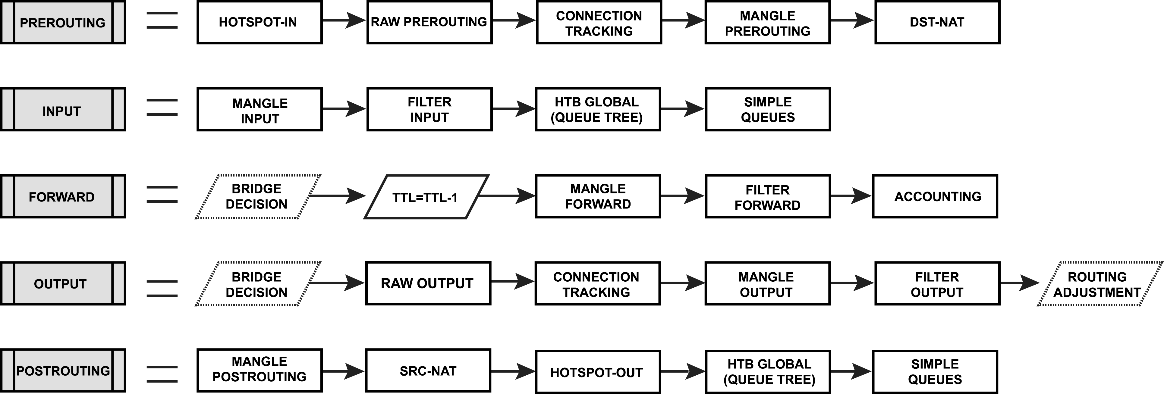
This small update with possible can someone help better understand the place of new blocks "RAW Prerouting" and "RAW Output".
download/file.php?mode=view&id=27228
Re: New Packet flow diagram
Posted: Tue Mar 21, 2017 8:56 am
by Nemiroff84
[quote="noviy"][/quote]
Can you place the diagram in visio format too?
Re: New Packet flow diagram
Posted: Thu Dec 21, 2017 4:45 am
by bajodel
This small update with possible can someone help better understand the place of new blocks "RAW Prerouting" and "RAW Output".
@noviy
I noticed only now your 2017/03 diagram update (I know, I'm late

) .. but I want to thank you for the brilliant work!! Now with new details and raw tables is really complete.
( & "UP" ..many others may have missed it)
Re: New Packet flow diagram
Posted: Sat Mar 23, 2019 12:43 am
by NoobJambon
Hello guys !
I'm looking at those packet flow diagrams and the exemple scenario and I was wondering : where does the traffic originating from the router itself appears ?
For example let's say I bind a dhcp-client to a vlan interface, what would be the path of a DHCP Request packet on those diagram ?
Re: New Packet flow diagram
Posted: Sat Mar 23, 2019 1:17 am
by BRMateus2
Hello guys !
I'm looking at those packet flow diagrams and the exemple scenario and I was wondering : where does the traffic originating from the router itself appears ?
For example let's say I bind a dhcp-client to a vlan interface, what would be the path of a DHCP Request packet on those diagram ?
Router originated packets are always output->postrouting.
Look at, where input are packets targeted exclusively to router (or not-NATted for example), and output are exclusively outgoing originated from router.
https://wiki.mikrotik.com/images/2/2f/Pfd.png (
https://wiki.mikrotik.com/wiki/Manual:Packet_Flow)


