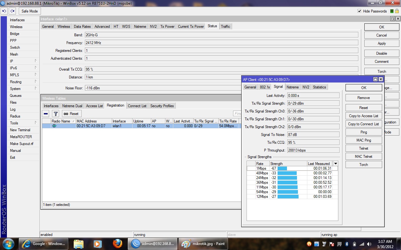
I only improved this product to focus on using it as Access Point Client
You must see my scanning lists
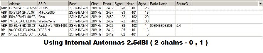
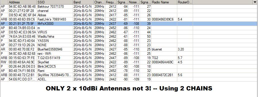
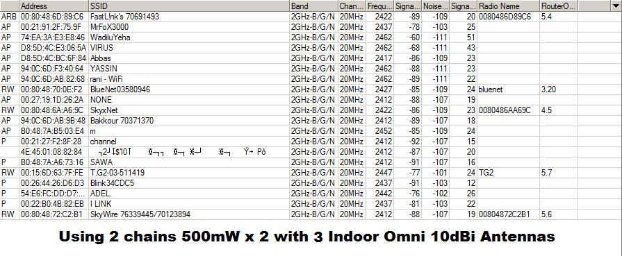
PLEASE FOCUS ON THE NOISE FLOOR HOW IT CHANGES!
This was in a hard area between walls and I was scanning from inside the house using the internal 3 PIF Antennas.
The same area .. same place but using only indoor 10 dBi Omni antennas not 3 as I have made sure to use CHAIN 1 with RX Chain 0.
Same Place .. Same walls but using the 3 x 10dBi Indoor Omni Antennas .
AS you can see some SSIDs are same and some of them are weaker , also others are stronger but I can see more neighbours … see it
If i use “AP BRIDGE” using 10 dBi Antennas then I can find my SSID 200m ~ 400m away from the house (NLOS) . If Im using the internal Antennas then I cant even find the SSID downstairs of the building anyway that was my project since I wanted to use this RB751U as AP CLIENT so I really wish if we could order directly from MIKROTIK but if they could accept some changing with some special in your PC BOARDS including 2 SMA Connectors because now I know why they had 2 antennas in one chain to improve it as well ( Double Power Gain ).
I was shocked because I was scanning my SSID from the Laptop and I was in the middle of alot of Noise and I was connected to RB751U Router but yeah the quality was okay not bad as far as I am away from the RB approx.300m!.
I have also used this product on 2.2GHZ , 2.3GHZ , 2.4GHZ and the signal was dropping 8dB to 10dB if we changed from 2.4GHZ to 2.3GHZ ..
2.2GHZ drops 20dB . I dont know where I read that this product works from 2.1 GHz till 2.7GHz maybe because the Power Amplifier inside the RB has Power Gain 30dB only on 2.4GHZ.
Im really happy with the results as in this case we can install more hotspots and our clients could use this RB751U.
The device really needs the external sma connectors to be a useful AP device. I’d happily pay an extra $20 for such a unit so that we can use them as access point hotspots in the bars, cafes etc rather than the 711 with internal case, pigtails etc were having to build.
Please look at the attached photo “RB751U-D.jpg” and look at it carefully and then you will notice that the each of three PIF antennas has 2 legs which i commented on each leg AS “RX & TX” ,“RX”, TX anbd the remaining legs are stated as “GROUND” which means we must connect the ground wire to GROUND and the center wire to TX or RX and ofcourse you could also add an SMA Connector to each pigtail but you must remove the 3 small antennas and you need to be really careful because sadly MikroTik made a thin board and really sensitive which I dont like at all .
When i tried to remove the 3 antennas or solder the cables , the place which I must solder on it , it was removed because it can not handle the heat pressure .
Sorry for the delay but I only made 3 products and the 3 products are placed somewhere and I cant grab them to take pictures inside but hopefully I would do it again next week.
I thought of doing like that because my target was to find a product with high power. When I bought this product at first I was thinking that we can install it for our customers to achieve inside their homes which made me think of installing it as AP Client since I am doing a new project here but with help from a company in USA .. calculating distances between Towers & Home Clients to reach something called “Near-Line-of-Sight” or “NLOS” since we are re-organizing TX Powers & adding more gain to Towers with less RX Sensitivity to avoid distortion .
By using 3 SMA Antennas ( VERTICALLY POL) , I am gaining more because we are targetting Laptops and thats why we are forced to use V Pols to achieve more gain and it works excellent with our solution but I assure to you that when I scanned from Rb751U .. I was only scanning from this board which has 3 SMA ANtennas and the SSIDs ofcourse everybody has V Pol though the default RB751u-2hnD Board has V , H Pols.
I wish if MikroTik would think of adding or replacing its amplifiers with something that allows 2.2GHz , 2.3GHz , 2.4GHz BANDS with the same TX Power! as I was noticed when I change from 2.4GHz to 2.3GHz then i loose 10dB and if 2.2GHz i loose 20dB and that is not fair because this thing would attract more business.
Im trying this week to finish designing an antenna sector for 2.3GHz and i think I’ve finished it but I must proceed building it for now to test it with RB751u to see how it works on 2.3GHz since all antennas or sectors are 2.4GHz & the 2.3GHz sector which i made has a very low VSWR 1.03 and 20dBi of gain.
I will see what would happen if 3 Sectors on 2.3GHz are aligning to the same direction. I could also install a switch between the “chain 0” antennas to have only 2 antennas.
Yes, I am not using MMCX Connector at all because .. For example , if you try to buy MMCX to SMA pigtail and try to plug it directly to MMCX External Connector then you’ll only get benefits of Single 500mW and no wonders why the length of the cable would affect on your Noise Floor as long as reflected Power would increase and therefore the Transmiss. Loss would increase too. How about if we want to just join chain 0 as well!?.
If we would like to attach 2 sma cables and solder them as well as we could also connect the MMCX Port then we will find that we are using “ANTENNA A CHAIN 0” & ANTENNA B CHAIN 1" which is not usefull at all though you could tick Antenna Type as ANT-A(TX)/ANT-B(RX) but beleive me thats not a good solution .. To get the maximum power you need to focus on “ANTENNA A CHAINS”.
Look at the Board circuit. There are 2 Power Amplifiers and each PA has 2 ways . For Example PA has to be on one chain which is “CHAIN 1” but using ANT-A & “ANT-B which is also the MMCX Connector”.
BTW .. You could also combine 2 antennas at chain0 using a switch TX/RX but apprx. 3dB loss appears and to me.
Maybe you would still ask why 3 Antennas?. AS I guess mikrotik thought of using chain 0 as Horiozontally Polarized and vertically Polarized as well to match all cases since we call it Multiple Input Multiple Output .Please look at the 3 antennas , you will find that you are looking into DIPOLES .
I was drawing and commenting on each antenna and I meant by TX or RX as conductor which the voltage is applied to.
I was in a hurry and didn’t mess with the shield and it worked great for me. Still working actually. I have no idea if this is recommended or not. Maybe some could elaborate?
Yes and please make sure the SMA connectors are positioned equally on the plastic case and try to position them really carefully because unfotunately the PC Board is really thin and especially the plastic case is really thin and easy to break it. I have doubled the thickness by applying a thin metal to keep it strong enough to avoid breaking it.
and what happens if we connect a 4th antenna to the mmcx connector.
does it make a difference??
or does connecting antenna to MMCX (antenna-b, chain 1) disable antenna-a, chain 1
No , it wont increase anything because Antenna-B is disabled and you can not enable ANT-A with ANt-B. What I understood that by default it has alittle loss but do not connect the 4th antenna to MMCX .. Noise Floor would be affected and therefore a decrease of the gain as well comes on the fronts.
Look what i did with the first RB751u-2HnD ..
Okay I tried to see what would happen if we removed MMCX Port and soldered again in reverse position , then connect MMCX pigtail to SMA but splitted and soldered one cable into 4 output conenctors with 4 x 5dBi SMA antennas but in this situation we disabled ANTENNA A chains 0 , 1 ( Unticked ) and ticked the ( CHAIN 1 ANT-B ) which restrict us to use 500mW.
I dont recommend to build it like that but the results you will get is almost close to 1 Watt if you positioned them equally and at the same side of the PLASTIC CASE but if you placed the antennas at different sides then the 4th antenna will get more Noise and split the power into dfferent angles which means some site surveys would decrease and others would increase as well.
If you want to try something new then use the dual chains and keep the vertical omni 3 x 5dBi or 10dBi as you wish but install another 2 SMA Connectors but positioned next to the 3 antennas because if someone has H Pols or V Pols then you can keep your gain stable and you will be able to server V , H .
I think i can take some pictures of the RB751U-2HnD at the Tower and maybe it will be something new to me as I am building an antenna sector with 2 N-Type Connectors H/V as I performed it on a program called 4NEC2 which gives about 20.1dBi especially made for 2.3GHz.
i see total TX Power as 30dbm with antenna -a and total TX power as 30 dbm with antenna -b enabled.
I don’t understand how it swaps from 500 mW to 1000 mW.
If you looked really carefully at the above attached pictures then you will notice at the board RB751 circuit SW702 (switcher). This will allow us to move from Antenna A to Antenna B which has only MMCX Port and only at this Power Amplifier which has 500mW .
Considering we have a source chip radio which has a few power and had 2 output lines and for each line has an amplifier with the same Power. LX5518 has a 30dB POWER GAIN at 2.4GHz only .Thats why you would get a high gain like 60dB using 2 chains and its TX Power depends whether you supply it with +3V or +5V so if we got a voltage meter and tried to read the voltage at the resistor which is responsible to supply LX5518. You will find that it is +5V DC which means that the PA is transmitting 28dBm but somewhere MikroTik thought of reducing it to 27dBm to get more efficiency% since it has an output power detector.
RADIO ----> LX5518 - A (500mW)----> SW702 ______ ANT A (CHAIN-0) PIF ANTENNA
|______ LX5518 - A ________________________ ANT B (CHAIN-1) MMCX
|
|___>LX5518 -B (500mW)----> TX
______ LX5518 - B ____________ RX
How do you get 1 Watt ?
Assuming we have Power Splitter/Combiner with 2 ways ( A , B , S ).
What would we get if we connected 2 Power Amplifiers?.
If we attached one radio to Port S as an INPUT POWER then the output ports A , B would split or divide 500mW to the antennas equally ofcourse if the 2 pigtails have the same cable length! but what if we attached 500mW Power to Port A and again attached another 500mW to Port B then the S-Port would combine the power as an additional power like PORT-A + PORT-B = PORT-S and this will yield TX 1000mW using 2 x 500mW but the software at MikroTik still shows 500mW and thats related to MikroTik.
It was working like that because the ATHEROS CHIP RADIO is built as Multiple Input Multiple Output (MIMO) technology which has 2 output. It allows MT to add 2 PA for each output though I couldnt find its datasheet but Im sure it has 2 outputs and I still wonder if MikroTik thought of building USB Devices with 1 Watts 2GHz.
What i have found earlier that to reach Non-Line-of-Sight then you need to increase your TX Power/ RX Sensitivity as well putting a multi polarized antennas not Dual Polarized.
Mr Ghassan, need help from you, i already mod may rb751u-2hnd and put 2 9dbi antenna at chain 0 and 8dbi antenna on chain 1 and set as AP Bridge (to share internet access wt my neighbour).
I put inside water proof box and install at my house rooftoop about 10 meter high.
The good thing I got very good signal and coverage. But the bad thing tx/rx ccq is very bad, if i inside my house I got good ccq around 80-100% but when I outside my house around 250meter from my house (signal block with some concreate wall) the tx/rx ccq drop to bellow 10% but the signal strengh is ok around 55%. When the tx/rx ccq drop bellow 15%, I intermitant can connect to internet but if bellow 10% cannot at all and wifi connection intermitant cut off.
To compare currently I use TP LInk wifi router(normal cheap wifi router) to share the net also put at my rooftop, but even the signal is low only get 10% but I still can surf the net.
So any solution for this bad tx/rx ccq? Any setting I need to tweek in wireless setting, curently I use default setting.
One more question is this normal when I see in ap client I saw tx signal strength 0 (only can see when open winbox in my laptop use wifi -wireless-registration-signal)