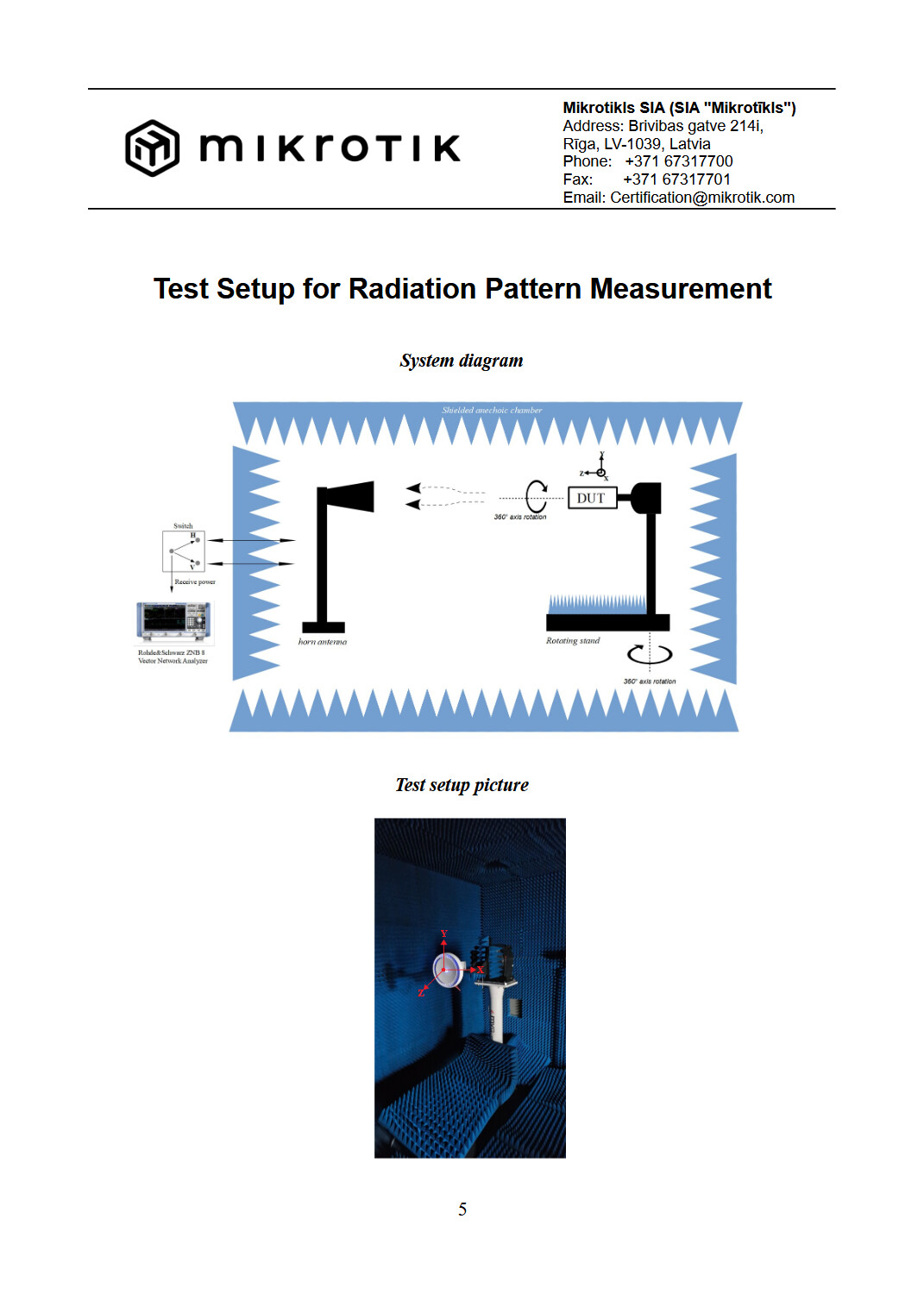
Thanks for your answer. Seems to me that both 5-GHz antennas appear to favor one side of the X-axis. That is why I was trying to find which physical side of the ceiling-mounted cAP ax corresponds to that side of the XY diagram?
@holvoetn
But that has already been categorized as a logical impossibility.
If that was true half the radiating power would be directed (through the ceiling) towards the floor above the device, and I refuse to believe that the good Mikrotik engineers could have designed that.
It Is much more likely that the shape Is that of a toroid in the horizontal plane and - without additional informations - there Is no reasons to presume any kind of directionality in the device patterns.
@george.gd
If there Is a weaker spot, It must where the box with ethernet sockets Is, see:
Thank you to all for your information. I could find the same doc in internet and send a question to mikrotik as following :
"Could you please clarify how the X and Y axes shown in the radiation-pattern diagrams correspond to the physical orientation of the cAP ax?
In particular, in the measurement setup shown on page 5, is the cAP ax mounted in the same orientation as recommended for installation on a vertical wall, with the Ethernet ports at the bottom?
If so, would this mean that +Y points away from the Ethernet ports and −Y points toward the Ethernet ports?
I would like to use the 5 GHz XY radiation pattern to determine the best rotational orientation when installing a cAP ax on a ceiling." and have no reply yet.
If somebody may know and share this I would appreciate.
Seems like PhD thesis level task.
Pattern is one thing to consider but have you simulated reflections from metal elements at the place of installation?
If radiation pattern is that critical so the edge cases solve your problem, you might be looking at it in the wrong way. You may even use the wrong device.
I would say that radiating patterns measured with high sensitivity equipment in special rooms can be - at the most - a rough guideline.
What happens in the real world Is that you have an assortment of different clients, additionally used in a variety of orientations and held at different heights, in and environment with fixed and movable obstacles and/or sources of reflections.
And the final goal Is to have these clients working as best as they can.
A laptop on the knees of a person sitting on a chair in the corner of another room at 8 m from the cAP may work better (or worse) than a smartphone held near the ear of a tall person standing in the middle of a room at the same 8 m distance but in a different direction.
Another issue with radiation patterns, provided by MT (via FCC ... I'd rather that MT provided them directly, as part of device documentation) is that they are still incomplete in several aspects:
they only show a few particular cross sections (e.g. XY, XZ and YZ planes) and not complete volumetric measurements. These provide way too little information to extrapolate radiation pattern in some arbitrary direction
they only show patterns at a few discrete frequencies used ... while in reality, antenna patterns tend to vary pretty wildly with changed frequencies
These issues apply equally to the "home AP" devices (such as cAP ... used in more or less omni-directional scenarios) as well as to the Pt(M)P devices (e.g. SXT) where knowing precise radiation diagrams, including frequency-dependant portion, can aide with optimizing physical placement (and limit usable frequencies if antenna radiation pattern exhibits a dip in certain spatial direction at certain frequency).
The same problems are present with "antenna gain" information ... provided information only rarely (and very incompletely) includes information about antenna gain at some particular frequency (well within operating range) ... which again can vary pretty much.