[admin@MikroTik] > ping 192.168.0.254
  SEQ HOST                                     SIZE TTL TIME       STATUS
    0 192.168.0.254                              56  64 16ms38us
    1 192.168.0.254                              56  64 17ms454us
    2 192.168.0.254                              56  64 15ms139us
    3 192.168.0.254                              56  64 6ms528us
    4 192.168.0.254                              56  64 16ms470us
    5 192.168.0.254                              56  64 16ms692us
    6 192.168.0.254                              56  64 16ms678us
    7 192.168.0.254                              56  64 16ms665us
    8 192.168.0.254                              56  64 16ms719us
    9 192.168.0.254                              56  64 16ms700us
    sent=10 received=10 packet-loss=0% min-rtt=6ms528us avg-rtt=15ms508us max-rtt=17ms454us

[admin@MikroTik] > /ip/arp/print where address=192.168.0.254
Flags: D, P - PUBLISHED; C - COMPLETE
Columns: ADDRESS, MAC-ADDRESS, INTERFACE
#    ADDRESS        MAC-ADDRESS        INTERFACE
0 DC 192.168.0.254  01:8D:12:8E:43:AC  lte2
One thing to note is:
I’d make sure you were NOT using ECMP routes – e.g. “+” in /ip/route/print mean you aren’t use that. I suspect both your APN profiles has a default-route-distance=2 for both LTE interface. Change one of the APN profiles to default-route-distance=3. That fact you see some pings, but not others, get through is pretty odd, and why I think ECMP may be involved.
Also, in the static route within the WAN2 route table, you want to use “192.168.0.254” as the gateway, not “lte2”.
One thing to note is:
I’d make sure you were NOT using ECMP routes – e.g. “+” in /ip/route/print mean you aren’t use that. I suspect both your APN profiles has a default-route-distance=2 for both LTE interface. Change one of the APN profiles to default-route-distance=3. That fact you see some pings, but not others, get through is pretty odd, and why I think ECMP may be involved.Also, in the static route within the WAN2 route table, you want to use “192.168.0.254” as the gateway, not “lte2”.
No matter how much I add APN for lte2, it is not saved. Probably due to the fact that it is registered in the usb modem Huawei E3372.
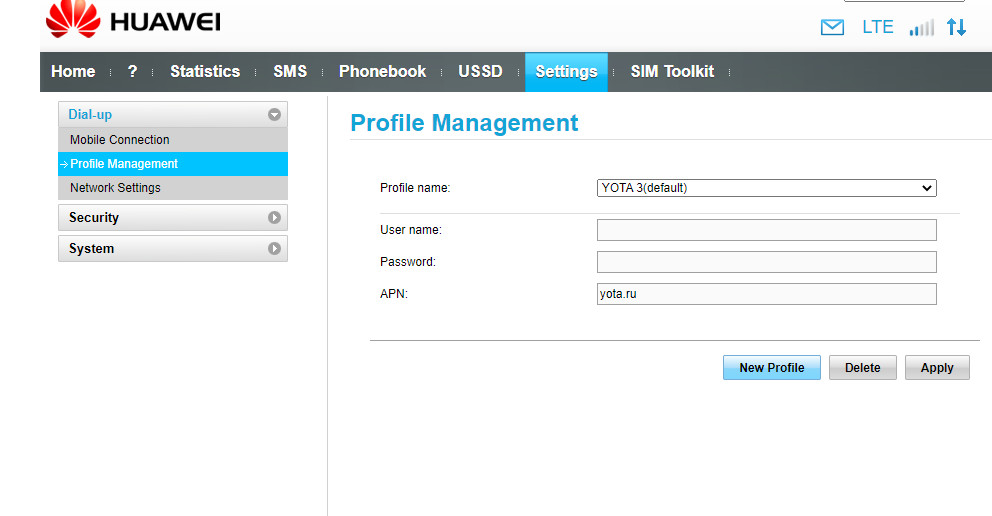
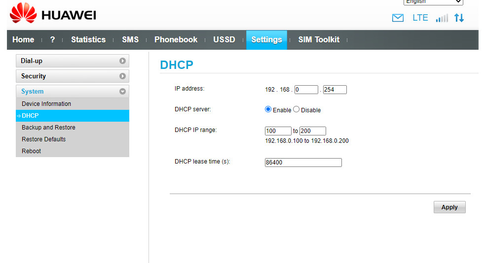
So if I get it right, the Huawei stick acts as a complete router with NAT and its own web management page, yet it doesn’t work. In that case, I’m not sure whether RouterOS is ready to handle such a device without trying to configure it. In fact, it should handle it like a plain USB to Ethernet adapter whose Ethernet side is connected to an external router, not as an LTE modem.
No idea whether something like that is possible in current RouterOS 7, i.e. whether it is possible to disable the LTE handling part. Worse than that, the configuration attempts most likely break something that otherwise works (as you’ve mentioned the Huawei thing to work in the other router).
I’m out of ideas - I neither have a device with USB port running RouterOS 7 nor this Huawei stick.
sindy thank you so much for your help! But I was sure that the Huawei E3372 usb modem would work. So many articles on the topic https://yandex.ru/search/?lr=213&clid=2224313&text=MikroTik+и+Huawei+E3372
now I don’t even know what to do next. I do not have a wired provider, and the choice of two operators is necessary for combining, summing, speed and as a fault tolerance option, it happens that one of the operators is unavailable.
You may be right, this is the complex ECM vs MBIM mode stuff I think. In ECM mode, it may not use APN settings since hotspot looks like ethernet-like interface. If that the case, the E3372 bridges the hotspot Wi-Fi to an ethernet interface via USB. Now most modems in ECM do require AT command to do stuff like set APN or read stats, but those happen via serial AT channel with ECM. But the interface would still appear under LTE based on USB device ID being associated with ECM.
But you change lte1 to use a distance of “1” in it’s APN profile instead, that avoid having two routes with the same distance in the /ip/route/print screen. Since you’re likely right lte2 settings are having no effect. But nothing stops you from changing the one that works (lte1) to use default-route-distance=1.
(Edited: upgraded to 7.1.2 already)
There were many LTE bug fixes since 7.0.4. Possible one of those fixes the E3372 with the Mikrotik.
The 3372 name is unfortunately common for a bunch of sub-models with different capabilities and firmware, so it is really hard to guess what exactly went wrong and at which side. I could not find a way to assign no APN profile to the inteface, nor to set an empty name of the APN inside the profile. I would have to have a remote access to the device to try some random experiments, but there’s no guarantee that I could make it work.
You can always put the old router between the Chateau and the Huawei stick, but that’s one Etherne port occupied on the Chateau and another 10 W or so of power wasted.
I continue to experiment with my set of devices and the possibility of combining 2 networks.
I flashed the Huawei E3372s usb modem with the Stick firmware, now the modem works in PPP mode (ppp-out1) and the ppp-out1 profile has its APN registered. The question is the same, there is a possibility of combining ppp-out1 and lte 1 and if so, how to do it.
I was only able to configure the ppp-out1 channel reservation by the modem and switching the sim provider.
Export
# feb/17/2022 12:52:26 by RouterOS 7.1.2
# software id = WPN3-SPNC
#
# model = D53G-5HacD2HnD
# serial number = E9CD0FA7F50B
/interface bridge
add name=bridge1
/interface lte
# A newer version of modem firmware is available!
set [ find ] allow-roaming=no band=1,7,20 name=lte1
/interface wireless
set [ find default-name=wlan1 ] country=russia disabled=no hw-protection-mode=rts-cts hw-retries=15 mode=ap-bridge ssid=CountryHouse tx-power=10 tx-power-mode=\
    all-rates-fixed wds-default-bridge=bridge1 wds-mode=dynamic wireless-protocol=802.11
set [ find default-name=wlan2 ] country=russia disabled=no mode=ap-bridge ssid="CountryHouse 5G" wireless-protocol=802.11
/interface list
add name=WAN
add name=LAN
/interface lte apn
set [ find default=yes ] apn=internet.tele2.ru default-route-distance=1 name=tele2 use-network-apn=no
/interface wireless security-profiles
set [ find default=yes ] authentication-types=wpa-psk,wpa2-psk eap-methods="" mode=dynamic-keys supplicant-identity=MikroTik
/ip pool
add name=dhcp ranges=192.168.10.2-192.168.10.254
/ip dhcp-server
add address-pool=dhcp interface=bridge1 name=dhcp1
/port
set 0 name=usb1
set 1 name=usb2
/interface ppp-client
add apn=internet.yota default-route-distance=3 dial-on-demand=no disabled=no info-channel=1 keepalive-timeout=0 max-mru=1476 max-mtu=1476 name=ppp-out1 phone=*99# \
    port=usb2
/interface bridge port
add bridge=bridge1 interface=ether1
add bridge=bridge1 interface=ether2
add bridge=bridge1 interface=ether3
add bridge=bridge1 interface=ether4
add bridge=bridge1 interface=ether5
add bridge=bridge1 interface=wlan2
add bridge=bridge1 interface=wlan1
/interface list member
add interface=lte1 list=WAN
add interface=bridge1 list=LAN
/ip address
add address=192.168.10.1/24 interface=bridge1 network=192.168.10.0
/ip dhcp-server network
add address=192.168.10.0/24 gateway=192.168.10.1 netmask=24
/ip firewall filter
add action=accept chain=input protocol=icmp
add action=accept chain=input connection-state=established
add action=accept chain=input connection-state=related
add action=drop chain=input in-interface-list=!LAN
/ip firewall mangle
add action=change-ttl chain=postrouting new-ttl=set:128 out-interface=ppp-out1
/ip firewall nat
add action=masquerade chain=srcnat out-interface-list=WAN
add action=masquerade chain=srcnat comment="default configuration" out-interface=ppp-out1
/system clock
set time-zone-name=Europe/Moscow
/system routerboard settings
set cpu-frequency=auto
There are two extremities - one is to keep using one of the WANs for all the connections as long as it works, and only use the second one if the first one fails, and the other one is to distribute the traffic among both of them per individual connection (so two consecutive reloads of the same web page from the same browser on the same PC may end up using distinct WANs). And then there’s the scale between those, where you can e.g. distribute the connections among the WANs solely based on the source address, i.e. the same PC in your LAN always uses the same WAN unless that WAN is broken; for some connections, you can override these rules and either prefer a particular WAN (i.e. still move the connection to the other one), or even never try the other WAN if the desired one is broken (the latter relates to cases like VPN tunnels you use for redundant remote access to your router, some ISP-provided mail or DNS services that only respond requests coming from addresses provided by the ISP, some IP telephony services, …).
The key to all this is policy routing - you create a dedicated routing table for each category of traffic (prefer WAN 1, prefer WAN 2, exclusively use WAN 1, exclusively use WAN 2), and you create rules assigning the routing table names depending on some other attributes of the traffic than the destination address alone.
In order to use policy routing for redundancy purposes, you have to activate a mechanism checking transparency of the WANs all the way to the internet and deactivate the routes if there is a problem.
Further reading is http://forum.mikrotik.com/t/advanced-routing-failover-without-scripting/136599/1 and http://forum.mikrotik.com/t/static-default-route-im-missing-something/119183/9
Specifically for PPP and LTE interfaces, before trying anything deeper, check what address is shown as network in /ip address print for rows related to those interfaces, and whether this address changes when you disconnect and reconnect the interface. The thing is that whilst with point-to-point interfaces it is enough to use the interface name as the gateway item of a route, for recursive routing, this was impossible in RouterOS 6, I’m not sure whether it has changed in RouterOS 7.
When disconnecting and reconnecting the PPP or LTE interface, the address is saved.
[admin@MikroTik] /ip/address> print
Flags: D - DYNAMIC
Columns: ADDRESS, NETWORK, INTERFACE
#   ADDRESS            NETWORK         INTERFACE
0   192.168.10.1/24    192.168.10.0    bridge1
1 D 100.81.172.225/32  100.81.172.225  lte1
2 D 10.104.162.215/32  10.112.112.139  ppp-out1
[admin@MikroTik] /ip/address> print
Flags: D - DYNAMIC
Columns: ADDRESS, NETWORK, INTERFACE
#   ADDRESS            NETWORK         INTERFACE
0   192.168.10.1/24    192.168.10.0    bridge1
1 D 100.81.172.225/32  100.81.172.225  lte1
[admin@MikroTik] /ip/address> print
Flags: D - DYNAMIC
Columns: ADDRESS, NETWORK, INTERFACE
#   ADDRESS            NETWORK         INTERFACE
0   192.168.10.1/24    192.168.10.0    bridge1
1 D 100.81.172.225/32  100.81.172.225  lte1
2 D 10.104.162.215/32  10.112.112.141  ppp-out1
[admin@MikroTik] /ip/address> print
Flags: D - DYNAMIC
Columns: ADDRESS, NETWORK, INTERFACE
#   ADDRESS            NETWORK         INTERFACE
0   192.168.10.1/24    192.168.10.0    bridge1
1 D 10.104.162.215/32  10.112.112.141  ppp-out1
[admin@MikroTik] /ip/address> print
Flags: D - DYNAMIC
Columns: ADDRESS, NETWORK, INTERFACE
#   ADDRESS            NETWORK         INTERFACE
0   192.168.10.1/24    192.168.10.0    bridge1
1 D 10.104.162.215/32  10.112.112.141  ppp-out1
2 D 100.81.172.225/32  100.81.172.225  lte1
sindy, you can write easier. After your last message, I’m at a loss as to what to do next.
Next, express what behaviour you expect from the “combination” of the WANs. The complexity or simplicity of the setup depends on what you want it to do.
sindy, I really wanted to build a configuration with traffic aggregation between both ppp-out1 and lte1. Indeed, in such a configuration, as far as I understand, everything will work even when one of the interfaces exits.
So no specific handling for specific traffic, ok. As for “everything will work”, the thing is that the LTE connection may be up but the data may not pass through (this is e.g. what my LTE operator does when the service is disabled because there wasn’t enough credit on the balance to renew the service for next month). That’s one example why checking of link transparency is important, otherwise the connections that choose that link will fail.
So I’d still use the recursive routing to monitor the transparency:
/ip/route/add dst-address=1.1.1.1 gateway=100.81.172.225 scope=11
/ip/route/add dst-address=9.9.9.9 gateway=10.112.112.139 scope=11
Then, I’d add the two routing tables, each with just two recursive default routes, one preferring the internal LTE and the other one preferring the USB one
/ip/routing/table add name=prefer-internal fib
/ip/routing/table add name=prefer-usb fib
/ip/route/add routing-mark=prefer-internal gateway=1.1.1.1 check-gateway=ping target-scope=11 distance=1
/ip/route/add routing-mark=prefer-internal gateway=9.9.9.9 check-gateway=ping target-scope=11 distance=2
/ip/route/add routing-mark=prefer-usb gateway=9.9.9.9 check-gateway=ping target-scope=11 distance=1
/ip/route/add routing-mark=prefer-usb gateway=1.1.1.1 check-gateway=ping target-scope=11 distance=2
Finally, I’d set up mangle rules to assign routing marks (routing table names) to traffic from LAN to internet:
/ip/firewall/mangle add chain=prerouting in-interface-list=LAN per-connection-classifier=both-addresses-and-ports:5/0 action=mark-routing new-routing-mark=prefer-internal
/ip/firewall/mangle add chain=prerouting in-interface-list=LAN per-connection-classifier=both-addresses-and-ports:5/1 action=mark-routing new-routing-mark=prefer-internal
/ip/firewall/mangle add chain=prerouting in-interface-list=LAN per-connection-classifier=both-addresses-and-ports:5/2 action=mark-routing new-routing-mark=prefer-internal
/ip/firewall/mangle add chain=prerouting in-interface-list=LAN per-connection-classifier=both-addresses-and-ports:5/3 action=mark-routing new-routing-mark=prefer-usb
/ip/firewall/mangle add chain=prerouting in-interface-list=LAN per-connection-classifier=both-addresses-and-ports:5/4 action=mark-routing new-routing-mark=prefer-usb
This setup should distribute 3/5 of the connections (not directly traffic volume) to the internal LTE and 2/5 to the USB LTE.
If 1:1 is enough for you, use just one rule with 2:0 and one rule with 2:1.
sindy, thanks a lot! Everything is written so accessible, for a simple user, thank you.
But I have trouble when I tested the disconnect / connection - the interface addresses did not change. And now, before making changes, I checked
/ip address print
and found that for ppp-out1 it changed to
1 D 10.104.162.215/32 10.112.112.141 ppp-out1
And if I register it now, and it changes again, then the scheme will not work. sindy, I’m sorry, what to do in such a situation?
You can try to set the gateway of the route to 9.9.9.9 to ppp-out1 instead of 10.112.112.xxx. If the routes via 9.9.9.9 remain available after that, great. If not, it will require a script in /ppp profile to update the gateway of those routes with the up-to-date one, in that case come back.
sindy, stumbled
[admin@MikroTik] > /ip/routing/table add name=prefer-internal fib
syntax error (line 1 column 12)
found
(Applicable for ROS7). Creating custom routing tables for each of the providers
/routing/table/add
but I can’t figure out with
/ip/route/add routing-mark
In ROS7, pre-creation of custom tables is required. Can you fix the config for version 7?
Sorry, my bad (or Mikrotik’s bad, for changing things without an actual purpose): it is now /ip/route/add routing**-table** whereas in mangle rules, it is still new-routing**-mark** like in ROS 6.
sindy, after much experimentation with the configuration, I came to the conclusion that I need a script to update the gateway in the profile / ppp routes to the current one. The addresses of the two interfaces change.
Strange. Have you tried to set the gateway of the route towards 9.9.9.9 to ppp-out1 and the gateway of the route towards 1.1.1.1 to lte1 as I’ve suggested?
The thing is that in RouterOS 6, the recursive nexthop search only worked if all the gateway parameters of the routes involved in the recursion were IP addresses, but I’ve just tried in RouterOS 7 that this limitation doesn’t exist any more (someone has mentioned here on the forum that something has changed in this part but I didn’t remember the exact details).
So try
/ip route set [find dst-address=1.1.1.1] gateway=lte1
/ip route set [find dst-address=9.9.9.9] gateway=ppoe-out1
If it works this way, you don’t need any script as the changing addresses of the two interfaces become irrelevant.
If it doesn’t, the check-gateway=ping mechanism cannot be used for the internal LTE interface because the network parameter of the /ip/address row is the same like the address itself, and the gateway of the default route added automatically is almost certainly lte1. So the script would only take care of the route via ppp-out1.
sindy, Thank you, it helped – it works like this!
I think this topic can be closed, the issue has been resolved.
Although there is one more question to clarify. If you bring back lte2, should this configuration also work?