If you don’t want to put the gateway in bridge mode, you can always setup one of the Mikrotik (best one you have, ac3 if I’m not wrong) as your main router behind ISP gateway, and the other to ac2 as CAPs, both connected to the Mikrotik. Then, open a DMZ to ac3 IP address, and even doing static routing on your gateway to avoid double NAT.
That way you will have the best of Mikrotik (ac3 commanding you network) and still don’t need to ask favors to your ISP.
Just bear in mind, in this mode, start the ac3 from default config, no from blank configuration, so you have at least a default firewall setup.
Hi @jhbarrantes I made it working with VLAN on top of VXLAN. However I noticed that when I connect to the guest wifi, speed test site like what fast.com shows only half of the download speed that I have - 150 Mbps instead of 300 Mbps. The bottleneck seems to be the VXLAN between hap-ac2 and hap-ac3. I tried with EoIP too, the same happens. I suspect MTU related problems, but I am not an expert in this area. Can you please take a look on the config, and highlight if I made something suboptimal? Thank you.
you are still keeping the same config, creating more and more complicated setup. Now, ac3 config has VXLAN and EoIP mixed, which is something I would never do. In addition, you have a VXLAN tagged in the bridge, but not in the bridge, which is weird to me (consider VXLAN as virtual ports you can add to a bridge to extend its L2 domain).
If you want to try with VXLAN, try, but start from fresh reset from default config. In addition, second device should start from no config at all, it makes no sense to have a second device acting as a router with full config when you are trying to achieve just the opposite (having them as CAPsMAN/CAP in the same L2 domain).
And, if I was you, I would completely get rid of this idea, put a single mikrotik device behind the gateway acting as a router, and forget about eoip, vxlan, etc; just using a pure CAPsMAN setup.
You said yo have a spare ac2. Right, use ac3 for router after the gateway (no matter if you have double NAT at the beginning) and just try to setup a simple 1 CAPsMAN + two CAPs setup. From there, you will have solid setup to work from. But please, start from scratch, reset ac3 keeping default config and 2xCAPs in CAPs mode, and work from there.
hi @jhbarrantes thanks for bearing with me and patiently replying to my messages. I understand your point, but I need hAP ac2 not in a simple CAP mode, because on that router I have a TV connected, that needs certain connectivity requirements. So another requirement of my setup is that hAP ac2’s configuration is not getting cleared.
The configuration I shared above works for CAPSman+CAP, so that is not the issue. Everything seems to work, except that problem related to speedtest. CPU is not the bottleneck, I checked that. I guess it is MTU related, or something is wrongly configured that both TX and RX on uplink ports are fully utilised.
What do you mean by that? Maybe that is my root cause.
I disabled EoIP interfaces, notice the disabled=yes
So yeah, things are working more or less, but on a client that connects to guest wifi (with VLAN 20), speedtest triggers something that fully utilizes some interface (I guess the uplink) and as the end result the download speed is only 150 Mbps instead of the 300 Mbps.
What are those requirements? A better understanding of those will help. Why can’t this be handled by the ax3? In hAP-ax3 you build you routing, with all the bells & whistles, and go L2 from there.
Having multiple routers in a home setup is not only overkill, but complex to maintain, unless you have pretty good experience on Mikrotik already. I still see you place at a single routing unit, with maybe different broadcast domains using vlans.. but not more.
Working and doing a good implementation in Mikrotik are completely different things. If you add a vlan as a bridge port, it works. It is the way to configure vlans? NO.
I suppose your issue is MTU, but you are causing it yourself for using tunnels (that always comes with a MTU drawback) in a local setup that doesn’t require them at all, making you to work with shorter MTU, mixing interfaces with default 1500 MTU with others that are not.
I insist, single router + 2xCAP, and implement vlans on your setup if need it. Then, manage all sort of tricks in AX3, not on CAPs. And forget about EoIP / VXLAN for your setup, are not need it at all.
@jhbarrantes
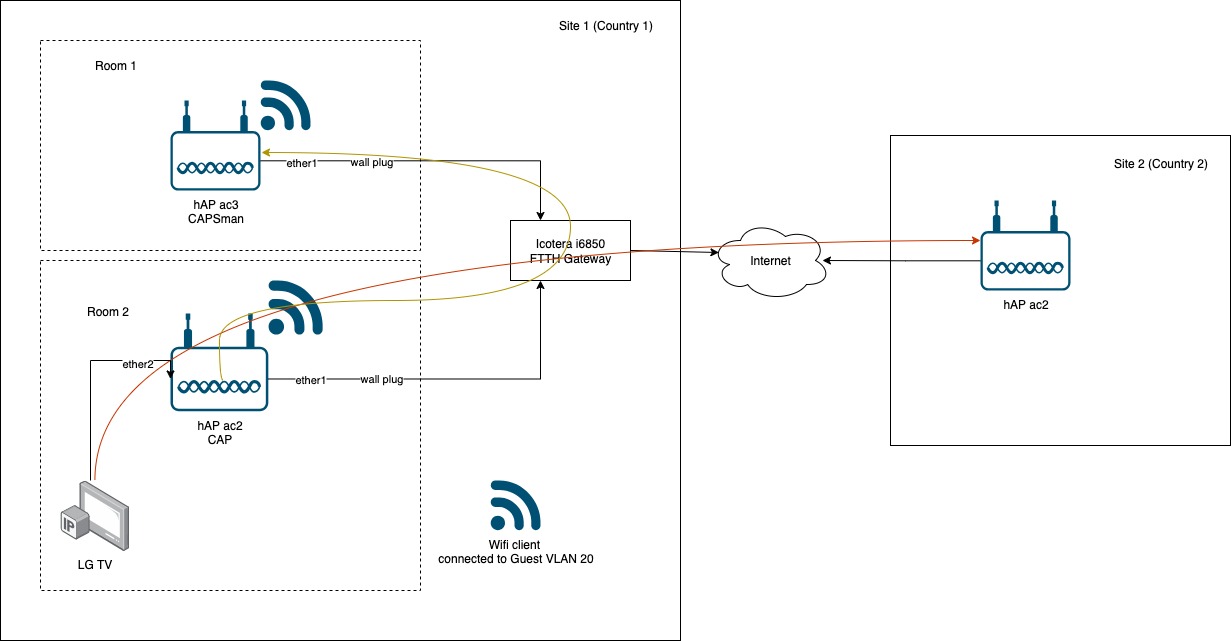
The use case is IPTV, and the TV in country 1 has to appear like it is in country 2. I use Wireguard + VXLAN for that purpose. (See orange flow on the diagram.)
The yellow flow is the local VXLAN for Guest VLAN 20. (To overcome the limitation that the FTTH gateway is not VLAN-capable.)
Since physically the devices are in separate room, each of them is connected to a wall plug that terminates in the FTTH gateway, that’s why I think I can’t just erase the configuration on hAPac2 - I would loose the Wireguard + VXLAN connectivity to Country 2.
So do you still see that my use cases (CAPSman + CAP, tunnel for IPTV to Country 2, Vlan Guest wifi) can be covered with only one device? Obviously for CAPSman + CAP I need minimum two devices. I need to put a device in room 2, because there is only 1 wall plug, but I have additionally to the LG TV a wired connected set to box as well. I think physically (cableing, wall plug) I am limited, right? Maybe I oversee something. Thanks for any hints.
No issues at all with this setup. You need to move the ac3 where the gateway is and connect ac2’s from each room into ac3, and ac3 to the gateway in DMZ and wifi off, and connect any other LAN cable from the home to the hAP-ac3, that becomes your main router.
Once done, you will have one mikrotik as main router + two CAPs.
Next step is to implement vlan filtering in all devices. You can create a separated vlan for any other traffic you want to isolate (such as the one to bring from other country), plus IoT devices or whatever you want to segment
Then, move the wireguard / VXLAN (I recommend to switch to EoIP, VXLAN doesn’t play well with multicast and replicate the traffic across all VTEPs) to the ac3. And, whenever you have to add the EoIP or VXLAN port into the bridge, do it with a specific PVID for a vlan, so that traffic get isolated from the other one.
On the CAPs, all you have to do is enable vlan filtering and extract this PVID in the port where you need it.
I insist, move all the routing to a main device, hAP-ac3 behind your gateway, and let the other one play as dumb APs.
Thank you @jhbarrantes for your proposal. I will try this setup as well, however I have limited space in the electrical cabinet where gateway is currently. Just a dumb question related to this:
Do I understand correctly, that CAPs ports can be still used for client devices, right? So I can still physically connect the TV and STB to the CAP’s ether2 and ether3, and ether1 is the “uplink” that terminates in hAP-ac3, right? In other words, when I enable dumb CAP, and reset configuration there, I can still have some configuration possibility to configure ports, and set PVID as you said, right?
Thanks, once we clarify this last question, I think it is clear how to proceed. I appreciate your support very much.
Yes, the ports on hap-ac2, by default, will extend your L2 domain from the hAP-ac3, so acting as a switch. When you implement vlans, these ports can be linked to any PVID and filter vlan on these devices, so actually you can manage different network segments with only one cable.
As these are two many changes, I suggest to go in different stages, like this:
save current config from hap-ac2 that contains wireguard tunnel and trick for IPTV. Don’t forget to save private key, so you can move this to hap-ac3
Reset all devices and let them run from default config (hAP-ac3) or CAPs mode (hap-ac2)
Do the interconnection and apply the DMZ to internet gateway to mikrotik hap-ac3 IP address. Consider to fix this IP on the gateway or convert this into manual IP rather than DHCP client on hAP-ac3
Check you network runs fine from this config, getting ready for the rest
Decide how to segment your network into different vlans. Assign subnets to each of them and get ready to go with vlan implementation.
Apply bridge vlan filtering configuration to hAP-ac3 and filter VLANs on bridges from CAPs for the ones you need to deliver by cable (wifi ones can be assigned from CAPsMAN if you still running with old wifi wireless driver), according to how you designed it in the previous step.
Create tunnels and EoIP/VXLAN to extend your remote network. Add the EoIP/VXLAN as a port into the bridge (MTU = 1500) and PVID= specific VLAN you decided. This VLAN won’t be addressed by the hAP-ac3, so all you have to do is declare this into bridge vlan table.
Propagate the chosen VLAN as tagged to the port that links with your hPA-ac2 where you are going to use it, and deliver this as untagged traffic for the final destination port (where the tv box is connected).
Thank you once again for your patient support and for the excellent network topology proposal you shared earlier. I’m happy to report that I successfully restructured my network based on your suggestions—and I’m really satisfied with the results!
I made one small adjustment compared to your original plan: I placed one of my hAP ac² units next to the FTTH gateway inside the electrical cabinet, instead of the hAP ac³. Unfortunately, I simply didn’t have enough space for the ac³, as it’s considerably larger. That said, performance-wise it’s not a significant compromise—the hAP ac² I’m using is from an early batch with 256 MB of RAM, which helps.
Since I don’t need wireless functionality from the hAP ac² placed next to the gateway, I disabled it as you suggested. Instead, the hAP ac³ is now one of the CAPs, which lets me take full advantage of its external antennas and higher gain. I also managed to power the central hAP ac² from the PoE out port of the hAP ac³, saving space in the cabinet and eliminating the need for a separate power adapter.
I also asked my ISP to enable bridge mode on my GW, so now as you suggested I got rid of double NAT.
I’ve attached the current configurations—I’d greatly appreciate it if you could take a look and let me know if there’s anything you’d recommend optimizing further.
In addition, I have a few small follow-up questions I’d love your advice on:
1. VLAN for IoT Devices in a CAPsMAN Setup
I haven’t yet created a separate VLAN for my IoT devices. I assume I can approach it similarly to the Guest network setup, but I’m a bit unsure how to proceed since I already use a slave configuration for the Guest network in my CAPsMAN setup.
Should I create a new provisioning rule and use a separate master or slave configuration for the IoT Wi-Fi network?
2. IoT Device Accessibility from Main LAN
Some IoT devices require my phone to be on the same network during initial setup. I understand in those cases I need to connect directly to the IoT Wi-Fi.
However, some mobile apps used for monitoring or managing these devices rely on local IP access (not cloud-based), and I’d prefer not to switch Wi-Fi networks just to access them.
If I want to allow one-way access—from my main LAN to the IoT VLAN—but still keep the IoT network isolated from the main LAN, would configuring firewall rules be the correct approach?
3. Best Practices: Firewall vs. Inter-VLAN Routing
More generally, what’s the best practice when it comes to managing communication between VLANs?
When should I rely on firewall rules to control access, and when is inter-VLAN routing preferred?
4. Restricting CAPs Discovery from Guest Wi-Fi
I noticed that when I connect to the Guest Wi-Fi, I’m still able to discover and connect to the individual CAPs (not the CAPsMAN itself) via Winbox.
Is there a recommended way to restrict this? I’d like to prevent clients on the Guest network from being able to see or access the CAPs directly.
Thank you again for all your help—your input has been incredibly valuable, and I’m learning a lot in the process.
If you go that way, I would suggest to remove the wireless package from this device, or replace it by the original wireless package, turning off the interfaces. The major drawback of hAP-ac2 is that flash space is only 16MB, what makes the firmware to go tighter than bolts on a submarine. Main package already contains CAPsMAN new driver, so there is no need to provide with a wireless firmware to this device if you are not planning to use its wireless capabilities.
Great, much more solid setup.
Router looking good in general. However CAP is not, regarding VLANs (common issue, specially since these guys does not support yet dynamic vlan assignment. Instead of playing with a “guest” datapath, just assign it directly where need it, placing the physical & virtual interfaces inside the bridge. So basically getting read of datapath and adding interfaces to the bridge as port manually, setting PVID=30 for guest ports. Should be something like this:
Salve config is an array of configurations, so you can place many, not just one. Would be done very similar to your guest wifi.
I use to create a list, such as “DIRTY_VLANS” and place in there all vlan interfaces that need the same behavior (at router). Then, create a one way only rule like this (to be placed at the bottom of your current firewall)
/interface list
add name=DIRTY_VLANS
/interface list member
add interface=vlan-iot list=DIRTY_VLANS
add interface=vlan-guest list=DIRTY_VLANS
/ip firewall filter
add action=reject chain=forward comment="dirty vlans: can only access internet" \
    in-interface-list=DIRTY_VLANS out-interface-list=!WAN reject-with=\
    icmp-admin-prohibited
This rule will allow devices in that list to go to the internet, but will drop anything else (communication between their vlans included, layer 3). In addition, as your main “vlan” (the “no vlan” = 1) is in LAN interface, anything starting from this VLAN will still be able to communicate with both of them, guest/iot.
Appart form that, for IoT only, you will need another trick: as you don’t want to be switching between wifi networks for configuring or accessing your speaker, lights, etc, you need to enable multicast repeater for this packages to filter between these two interfaces (bridge / vlan-iot) and allow multicast communication for them in input chain (the router itself). In summary, this two options:
/ip dns set mdns-repeat-ifaces=bridge,vlan-iot
/ip firewall filter
add action=accept chain=input comment=allow-multicast-from-iot \
    dst-address=224.0.0.251 dst-port=5353 in-interface=vlan-iot protocol=udp \
    place-before=[find comment="defconf: drop all not coming from LAN"]
In general I would say you are pretty good to go with the firewall filter rule I mention. How
ever, I used to do a fine tuning for restricting a bit more vlan-guest interface. I normally do 3 additional things:
prevent this vlan from learning ARP.
learn ARP only if the client was added by dhcp server with a short live (30min, 1h… around)
declare this network as /32 for dhcp, meaning clients won’t even have broadcast possibilities (some stuff may break because of this, for example Nintendo Switch doesn’t work well with this setup). Also, declare public DNS entries, so you don’t need to grant input access for this vlan at the router (DNS cache from router itself)
This will prevent people on your wifi network to fire fing or any other network analysis tool and prevent them to use a spoofed static IP/MAC, as ARP table won’t contain this if address/ARP was not added by DHCP server. In summary, I always declare guest networks like this: