off topic, FYI, I am at the stage already where I have 2 pairs of glasses, one for every day use and another for reading, it definitely helps, but unfortunately not in all scenarios
@peson, I read up a bit more on the horizon (I just wonder why these things are not covered in training / certification classes) and yes, will definitely use it.
Split horizon is covered in the MTCINE training (https://mikrotik.com/pdf/MTCINE_Outline.pdf)
I teaching it in the MTCNA classes I have since it’s a very useful feature when configuring port isolation which is common used in ISPs networks.
Of topic:
I still have only one pair of glasses, but I need to take them off when reading
Aaahhhh, that’s good to know, if all works out well, I will be attending MTCINE end July 2018. Sounds like an awesome course looking at outline, very excited
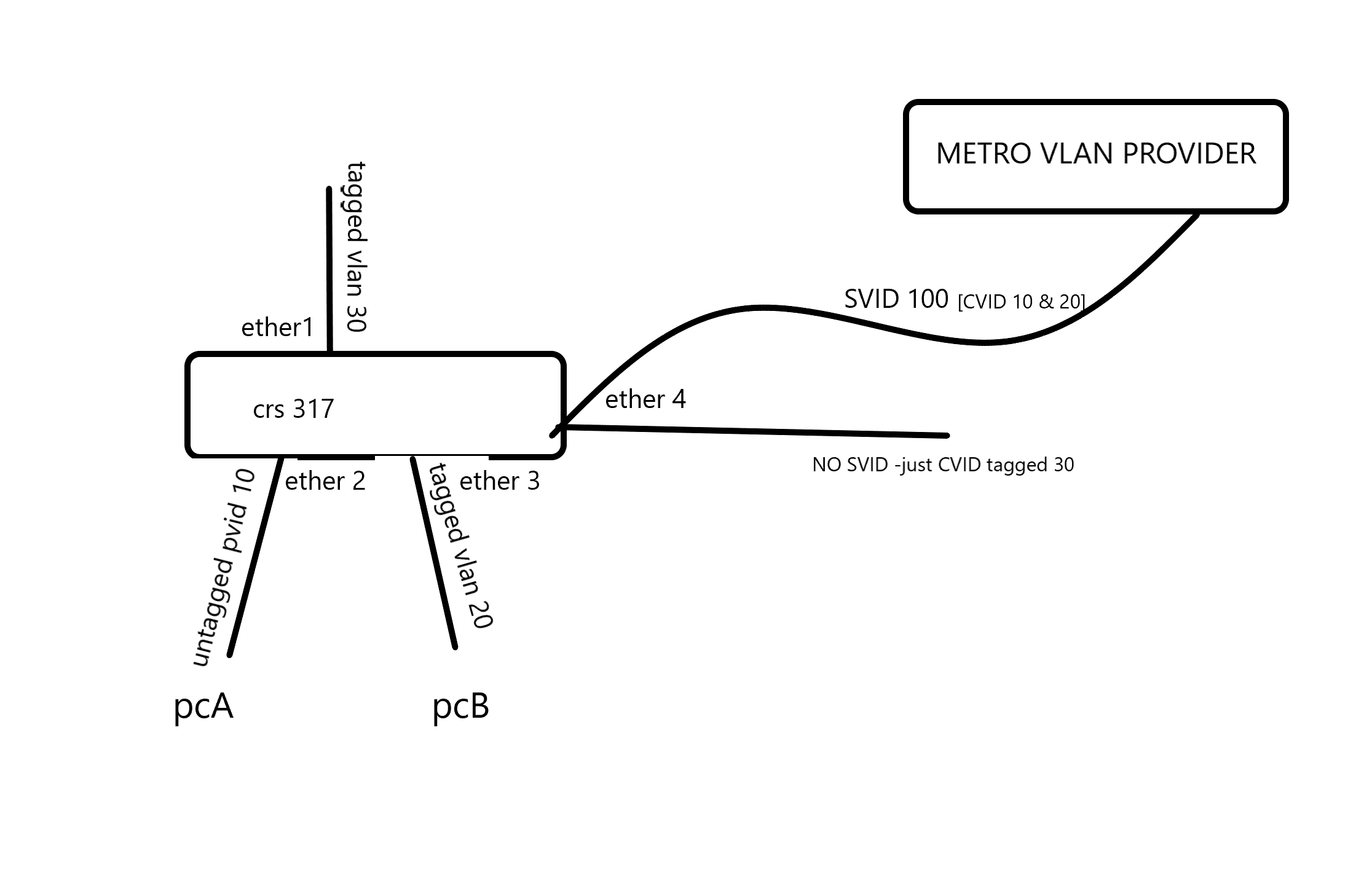
I’m looking for a qinad solution aswell. Currently I’m running 2 x CRS317 with a metro vlan provider in between them. There are several vlans on both sides that require to be connected by the s-vlan together. I’m running the vlan aware bridge configuration on both CRS’es. Some of the vlans are entering the device as tagged and some as untagged. The complex part is ether4. I thought it would be a good idea to create seperate bridges, but ether4 cant be attached to both bridges at the same time. See also attached image.
Anyone got a configuration suggestion / example?
I’m afraid none of the currently available Mikrotik products can fulfil your requirement completely in hardware without using crude hacks, at least because you need to add/remove two tags on the path between ether2 and ether4, whilst all the bridge implementations cannot add more than one tag on ingress and remove more than one tag on egress. So if you need to make use of the 10 Gbit/s bandwidth of the uplink, you may have to stack two CRS317, unless the partitioning of the switch chip and VLAN filtering is so good that you can connect together two ports of the same switch belonging to different partitions without creating a forwarding loop (you need per-VLAN forwarding tables in the switch chip as a minimum, plus you probably need that no VLAN ID is used for both a C-VLAN and an S-VLAN as the switch chip likely only uses the VID as an index to the table, not the tag type).
The topology would be the following:
S-bridge C-bridge A
║ ║
║ ║—access—
║—access—~====trunk===║ PVID 10
hybrid ║ PVID=100 VID 10,20 ║
===VIDs 100,999===║ ║===trunk====
PVID=999 ║ ║ VID 20
║
║ C-bridge B
║ ║
║—access—~====trunk===║===trunk====
║ PVID=999 VID 30 ║ VID 30C-bridge B is only necessary to prevent ingress of frames tagged with any other VID than 30 as S-bridge only cares about S-tags.
If you don’t need the full 10 Gbit/s speed (actually even just 1 Gbit/s may be too much to expect), you can implement a similar topology using software bridges and see whether the CPU will cope with the traffic or not. In this case, instead of cables between ports, you would use /interface vlan:
I understand the description in the manual you refer to in such a way that tag-stacking=yes only makes the /interface bridge port handling ignore the already existing tags on the ingress frames even if the topmost ethertype of the ingress frame matches the ether-type of the bridge and always act as an access port, i.e. add another tag in front of the existing one on ingress. But still it is just a single tag to be added on ingress and removed on egress, not two. Whereas in his post above, @deepmedia asks for adding a C-tag 10 to tagless frames received at ether2 and then adding also an S-tag 100 before sending them out ether4, so two ingress crossings of bridge (or switch) border are required.
So a single bridge approach could only work if you could add two tags in a single ingress handling step, but the switch chip of the CRS317 doesn’t provide such (rarely required) functionality in hardware, so even if it was implemented to the bridge, the throughput would still be limited by the CPU power and by the bandwidth of the internal connection between the switch part of the chip and the CPU’s packet interface.
I suspect from the feature overview on the respective manual page that the switch chips used in CRS1xx/2xx can add both a C-tag and an S-tag in a single ingress step, but 1) I don’t have a possibility to test this practically and 2) these devices have just up to two 10 Gbit/s ports so the bandwidth limitation might still affect @deepmedia’s use case.
Without tag-stacking option on the vlan-gs-ser port everything seem to work fine, but as soon as I enable tag stacking it got broken. Anyone got an idea?
I think you missundersstand the tag-stacking feature.
From the example on page: https://wiki.mikrotik.com/wiki/Manual:Bridge_VLAN_Table#Tag_Stacking
“What we want to achieve is that regardless what is being received on ether2 and ether3, a new VLAN tag will be added to encapsulate the traffic that is coming from those ports. What tag-stacking does is forces a new VLAN tag, so we can use this property to achieve our desired setup. We are going to be using the same configuration as in the Trunk/Access port setup, but with tag stacking enabled on the access ports:”
In your example, if 309 is the outer tag and sfp-sfpplus1 is the port to metro provider, it would be something like:
The main reason I didnt use pvid 309 on the endports is the fact we have untagged traffic that needs both an inner and outer vlan tag. Is there a way to double tag them? Or do you suggest to always tag all traffic on the Customers side?
That’s what I’ve tried to explain before in post #49 - it makes no difference whether you place an S-tag over an existing C-tag or whether you nest two C-tags, the real problem is that only a single tag can be added to a frame at ingress and none at egress, and just a single tag can be removed from a frame at egress and none at ingress. So when a tagless frame comes in through ether2, you can tag it with C-VID 10, but all the way to the wire connected to ether4 there is no place where you could add the other tag with S-VID or C-VID 100, unless you cascade two bridges as in my drawing.
If you can make all the customers send you only C-tagged frames, you’ll be in a better position because you’ll only need to add the outer tags, so in this case tag-stacking=yes will ensure that the existing C-tags of the ingress frames will be ignored and new C-tags will be added on ports configured as “untagged”. But if you set the ether-type=0x88a8 on the bridge, you don’t even need the tag-stacking=yes setting because the C-tags (0x8100) of ingress frames will be ignored because the bridge won’t recognize frames with ethertype 0x8100 as tagged ones.
Sindy, that’s exactly what I was already thinking. 1st of all I will start by making all my traffic towards and from our customers tagged. We’ll see if that will work out. Thanks!
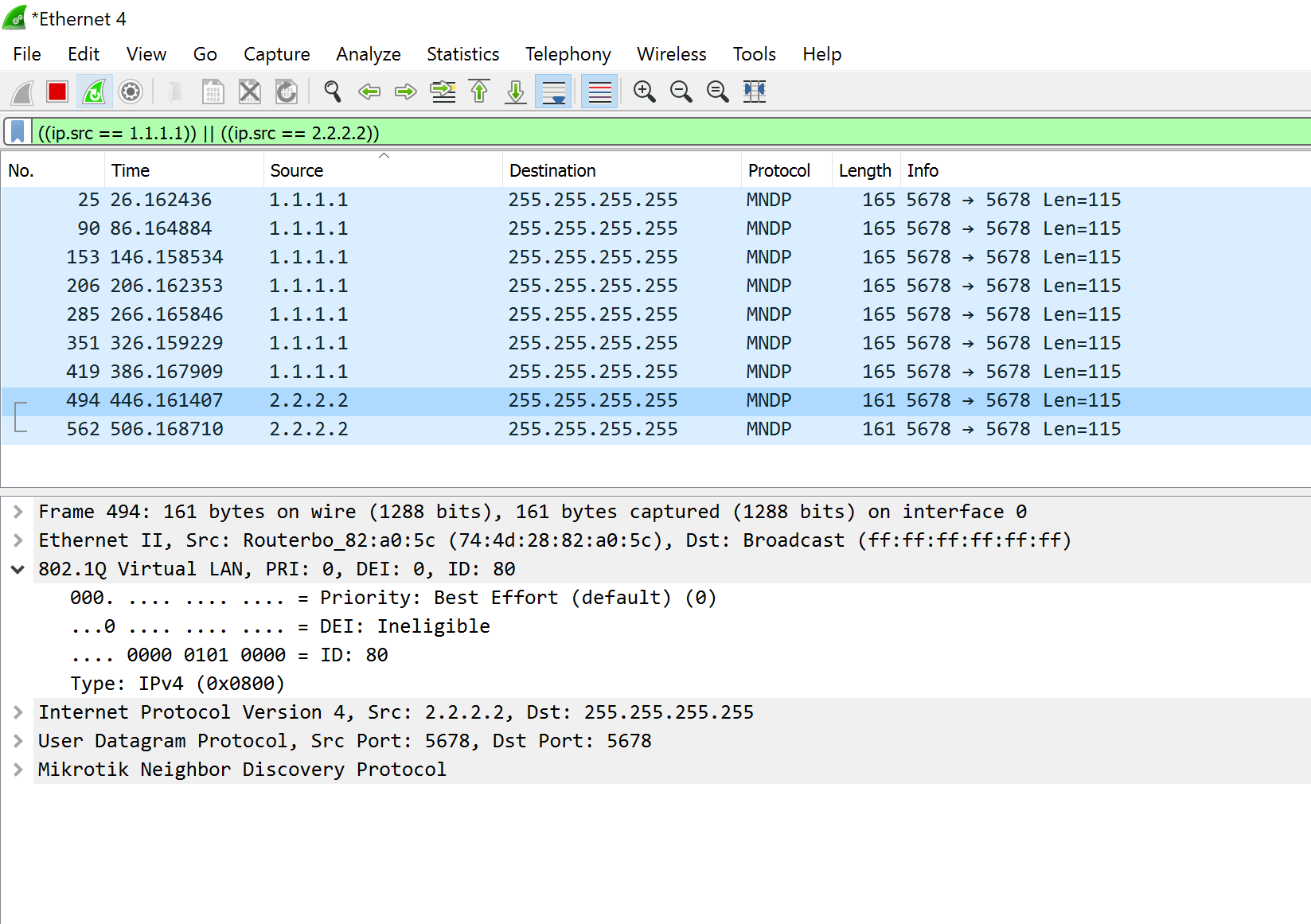
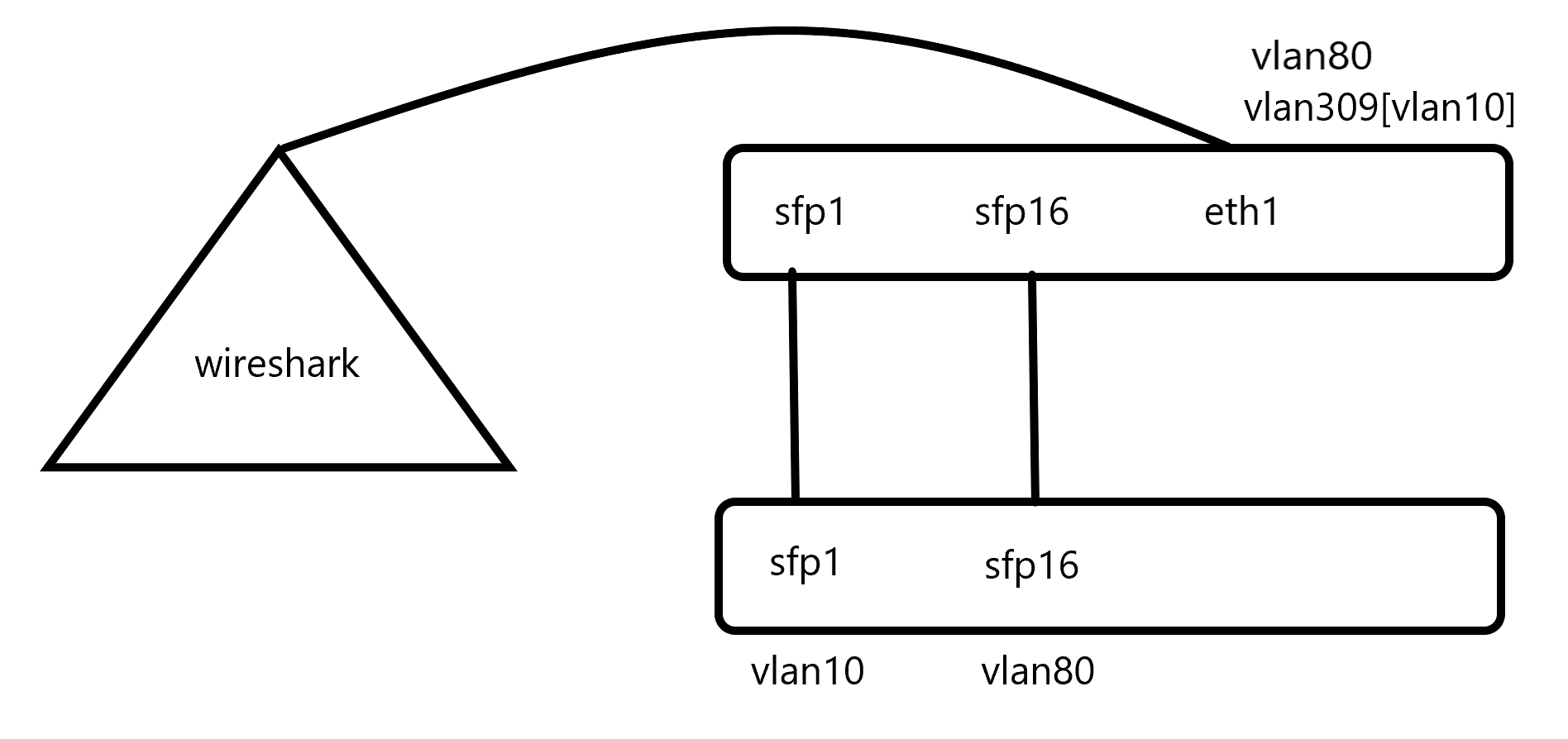
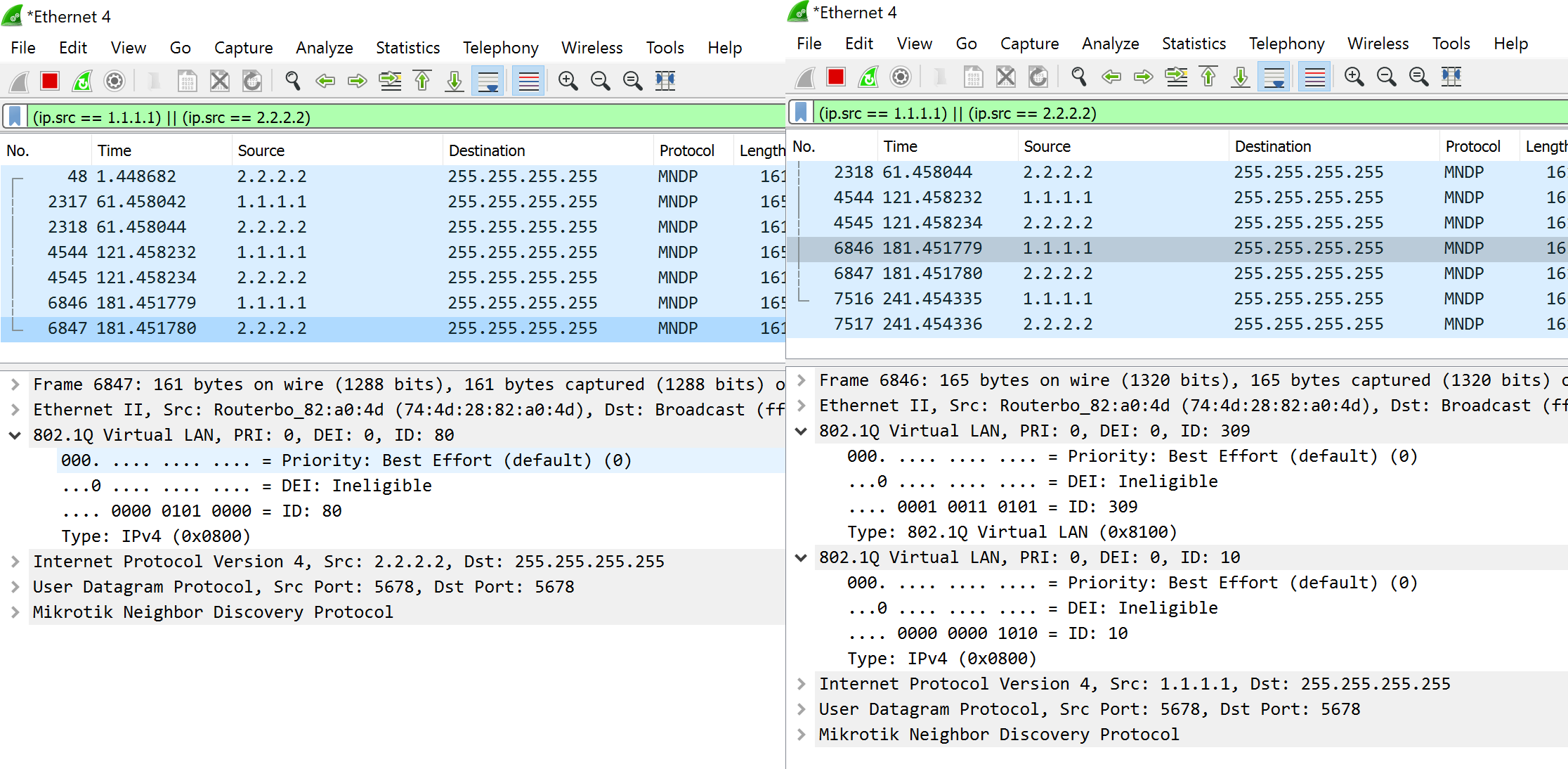
Whenever all cables are connected only the double tagged traffic gets forwarded to the wireshark (see image)
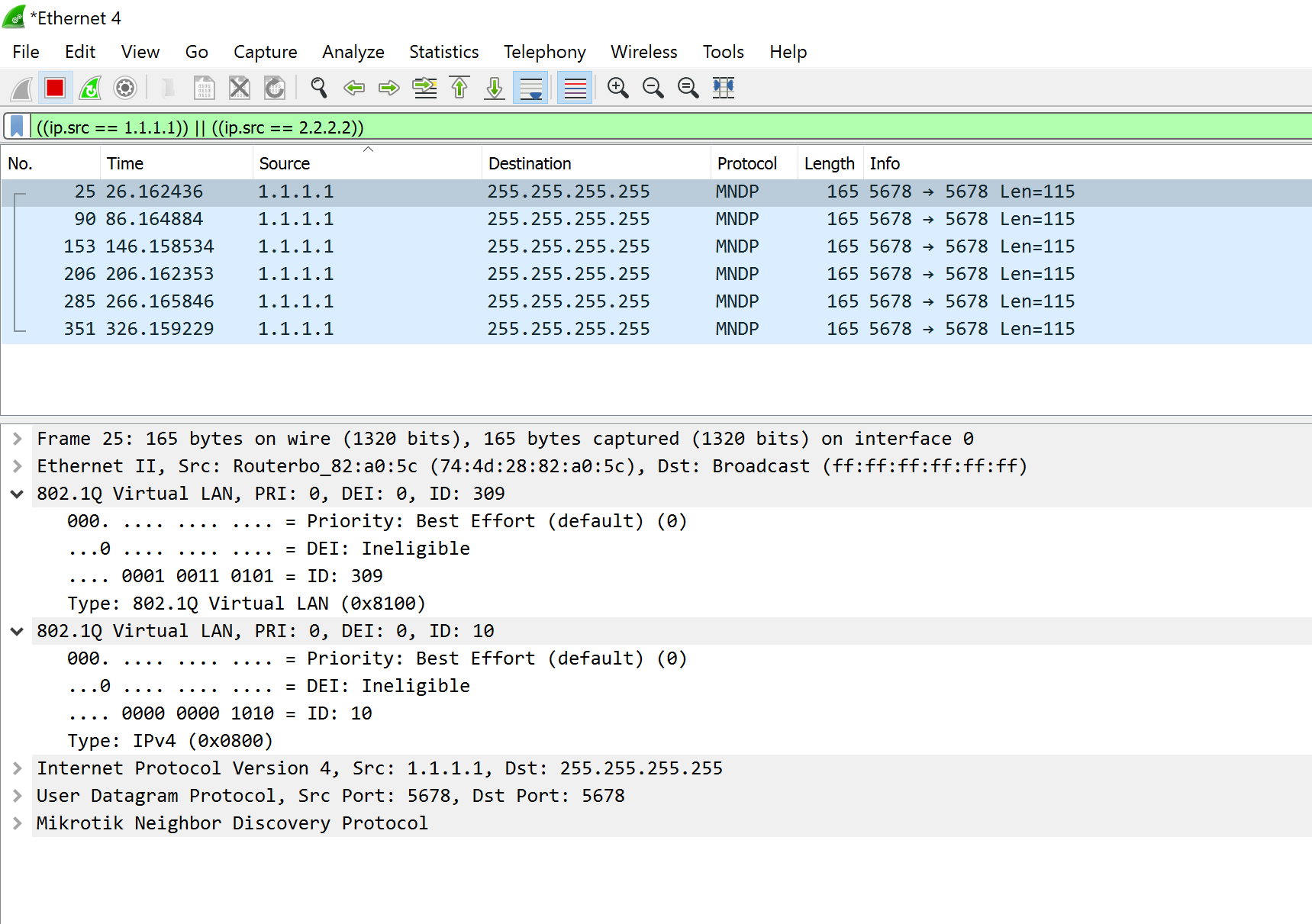
When disconnect sfp1 cable the single tagged traffic gets forwarded (see image)
Is there any workaround you guys might think of? The only requirement is the fact that single and double tagged traffic needs to be on the same cable (because of the carrier who is providing these vlans)
I’d have to see your setup hands-on (but I don’t plan to drive by any time soon), but I think you are missing one basic thing about L2 - in addition to VLAN-tagged traffic, there are also VLAN-agnostic protocols running on switches, among which STP is the one which causes this issue. Whenever you connect two L2 devices together by more than a single logical link (a bond of several physical links behaves as a single logical link), you have to address the omission of the L2 protocol designers which is the absence of any TTL field in the L2 header. In another words, you have to prevent loops in the logical topology by dynamically disabling all logical links except one. So although you only permit one VLAN on the physical link between sfpplus1 and only permit another VLAN on the physical link between sfpplus16, the RSTP protocol which runs on the bridges by default still only permits one of these links to be active at a time whenever both are physically connected.
So setting protocol-mode at both bridges (upper and lower) to none might resolve your issue, but it may also cause a broadcast storm if eventually some frames leak the wrong way and loop back through the other link. So if this happens, you’ll have to set up also split horizon, preventing any frame received on sfpplus1 from being sent out via sfpplus16 and vice versa, whereas ether4 on the upper CRS and any port except sfpplus1 and sfpplus16 on the lower CRS will be able to forward frames to/from both sfpplus1 and sfpplus16.
Other than that, I’m afraid that in order to make it work in both directions, the second row in /interface bridge vlan in the upper CRS configuration has to be changed to add bridge=bridge tagged=bridge untagged=sfp-sfpplus1 vlan-ids=309. The pvid parameter of /interface bridge port row controls the ingress handling; the position of the interface on the tagged or untagged list on the vlan-ids row in /interface bridge vlan controls the egress handling. For the upper CRS, VLAN 10 doesn’t exist at all, it only knows about VLAN 309 and VLAN 80.
Your suggestion turning off RSTP works… see image! Allthough I’m very excited to implement this on the network, on the other hand I am a little scared for broadcast storms as you suggested. Is there a way to verify / monitor this? And if this is the case, how to prevent it?
Oh and btw, In my previous post the last rule of the following config fell off by copy pasting, so current config about vlan statements is:
Replace the last two lines above by the single one I’ve suggested - add bridge=bridge tagged=bridge,ether1 untagged=sfp-sfpplus1 vlan-ids=309. As said, VLAN 10 is invisible to the upper CRS, it is just a payload inside VLAN 309 like any other.
In the configuration-to-be all ports will be added to a single bridge, with the protocol-mode set to none. No other bridges, no tagless or untagged (except for the stacked ones) will be accepted onto the switch. I am probably safe when all connections are managed and connected by myself By the way: it servers as a core/metro switch to connect the other datacentre to the primary one.
Well, I’m not really sure how exactly the switch chip handles ingress frames which are not Ethernet II but 802.2 (i.e. the first two bytes following the MAC addresses represent frame size, not content type), i.e. whether it deems them “untagged” or rather “neither tagged nor untagged”. And there are not just STP frames, some switch vendors use their proprietary frames for loop detection, which may take the long path provider_switch → upperCRS.ether4 → upperCRS.sfpplus1 → lowerCRS.sfpplus1 → lowerCRS.sfpplus16 → upperCRS.sfpplus16 → upperCRS.ether4 → provider_switch and make the provider switch shut down the port. In worse case, the adjacent switch would not detect a loop and disable the port but frames which escape the ingress filtering would circulate there forever (as they have no TTL field to be used to count hops), gradually seizing all the bandwidth. Candidates are not just broadcast/multicast frames but also frames towards unicast MAC addresses from which an ingress frame never comes so the switch cannot associate them with a port.
So to prevent this from happening, the port isolation needs to be set at the more distant switch from the source (so against loop detection/eternally circulating frames coming from the provider switch, the lowerCRS needs to have sfpplus1 and sfpplus16 isolated from each other; against loop detection/eternally circulating frames coming from the customer switch, the upperCRS needs to have sfpplus1 and sfpplus16 isolated from each other).