This sounds like an understandable misunderstanding  MLPPP indeed stands for “Multi-Link PPP”, but nevertheless it can be used even on a single link. The benefit of using MLPPP on a single link is that it allows to split large payload packets into multiple transport ones that do not exceed a certain size. So instead of fragmentation of the transport packets at IP level, which can cause packet loss because non-first fragments are treated badly in some parts of the internet, the payload packets get split. So the packet rate still doubles like in case of IP level fragmentation, but other negative effects of fragmentation are suppressed.
In routerOS, a real multi-link operation is only supported for PPPoE client, which isn’t helpful for your use case.
So the first thing I would try would be to use a single L2TP/IPsec tunnel with MLPPP enabled; to enable MLPPP, you have to set, at both the client and the server, max-mtu and max-mru allowed for the transport packets to something like 1300 (it can be fine-tuned later but for most traffic a small max-mtu doesn’t make much difference as it doesn’t matter whether you split a 1500-byte payload packet into a 1000-byte one and a 500-byte one or into a 1499-byte one and a 1-byte one) and mrru to 1504.
If that is not sufficient (the per-flow bandwidth limitation is still in place), you need to distribute the transport packets of the same L2TP flow among multiple unerlying IPIP tunnels, each of them encrypted using its own IPsec tunnel, same like we did with EoIP. You can keep the multi-EoIP setup in place, add the multi-IPIP one to it (using the same transport addresses like the EoIP tunnels do), and add routing tables and mangle rules to evenly distribute the traffic between the L2TP client and the L2TP server among those IPIP tunnels. You cannot use ECMP (multiple gateways for the same route) as route caching would cause all packets to use the same IPIP tunnel.
- [quote=“, post:101, topic:139236”]
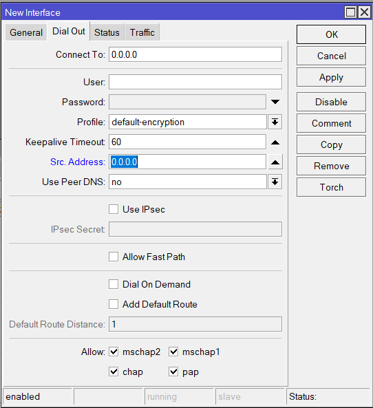
So how shall my L2TP tunnels look like on initiator and responder side (connect to, allow fast path, use ipsec, user)?
[/quote]
There will be just a single L2TP tunnel even if distribution of the traffic over multiple IPIP tunnels will be used. You will have to link the L2TP client to some local address c.c.c.c at router C - client (by setting src-address=c.c.c.c), and let it connect to some local address s.s.s.s at router S - server; at router C, the routing to s.s.s.s will be controlled by the routing tables and mangle rules, and so will be the routing to c.c.c.c at router S. There is no need to assign an address to each of the IPIP tunnel interfaces, I even prefer to assign s.s.s.s and c.c.c.c to port-less bridge interfaces than to assign them to any of the IPIPs. The user and password of the /interface l2tp-client row on C must match the name and password of a /ppp secret row on S.
- [quote=“, post:101, topic:139236”]
I guess original responder shall be the L2TP server, and initiator shall be the L2TP client. Is this assumption correct?
[/quote]
Technically it is not mandatory in this setup with the IPIP tunnels sandwiched between L2TP and IPsec, but I would also colocate L2TP server with IPsec responder.
- [quote=“, post:101, topic:139236”]
Shall I still use “manual” IPsec tunnels for this artificial MLPPP with multiple L2TPs?
[/quote]
Yes, as said above, keep the “manual” IPsec tunnels you have, and just add IPIP tunnels in parallel to the EoIP ones (you can remove the EoIP ones in future if this approach proves better).
- [quote=“, post:101, topic:139236”]
How can I “connect” IPsec tunnels (previously they were connected via IP address to the EoIPs) to L2TP connections? By doing the same with IPIPs?
[/quote]
There will be no direct relationship between the IPsec and the L2TP. The IPsec encrypts the transport packets of IPIP that flow between their transport addresses; the payload of IPIP will be the transport of L2TP, with an unrelated set of addresses (this is mandatory - c.c.c.c and s.s.s.s must not match the IPsec policies)
- [quote=“, post:101, topic:139236”]
What kind of mangles shall I create to distribute traffic between L2TPs? Like, defining routes, and use some IP header field (DSCP)?
[/quote]
Just as many routing tables as there are IPsec-encrypted IPIP tunnels at each device, with a single default route each, each using another IPIP tunnel interface as gateway. And then, mangle rules in chain output will assign the corresponding routing marks to packets from c.c.c.c to s.s.s.s (at C) and from s.s.s.s to c.c.c.c (at S) using the nth match, to distribute the LT2P transport traffic evenly:
/ip route
add routing-mark=via-ipip1 gateway=ipip1
add routing-mark=via-ipip2 gateway=ipip2
add routing-mark=via-ipip3 gateway=ipip3
/ip firewall mangle
add chain=output src-address=!c.c.c.c action=accept
add chain=output nth=3,1 action=mark-routing new-routing-mark=via-ipip1
add chain=output nth=2,1 action=mark-routing new-routing-mark=via-ipip2
add chain=output action=mark-routing new-routing-mark=via-ipip3
- [quote=“, post:101, topic:139236”]
Both IPIP and L2TP client has an option to specify IPsec secret. As I have manually created IPsec tunnels, I’m assuming I don’t need to set these, is this correct?
[/quote]
You even must not set these, as it would create another set of peers and policies that could interfere with the manually configured ones.
- [quote=“, post:101, topic:139236”]
So IPsecs are built up, they will encapsulate IPIP, and with IPIP addresses I have to create L2TP connections?
[/quote]
As stated above, do not link the c.c.c.c/32 and s.s.s.s/32 addresses to the IPIP interfaces, use some empty bridges for that - again, it’s just for clarity reasons, technically you can attach them to any of the IPIP tunnel interfaces.