

Hi folks,
I am completely new to the Mikrotik world, but not quite new to the Networking world (10+ years as a Network & Security Engineer, Cisco and Radware Certified, etc.)
While playing with my new RB3011 (FW 6.46.8 - I can’t upgrade to a newer release as they don’t support/recognise the SFP provider by my ISP), I discovered many neat features and frankly I’m quit impressed with the device RB3011 so far. Especially for the price!
However, there is one thing I can’t get to work and I saw that others have also struggled according to diverse forum posts.
As the device is lacking a proper Out-Of-Band Management port, I was planning to use one of the ethernet ports (i.e. Eth10) as a pure mangement port, whose IP would not be routed on the Mikrotik. One way of doing this would be to create a vrf (I will probably do so), but even from a pure routing perspective there is something I don’t understand.
Let’s say for instance I have the following L3 interface config:
eth9: 192.168.88.1/24 (the default Management IP address)
eth10: 10.0.0.1/24
then, I let’s say I have 2 dedicated bridge interfaces, each linked to a single physical interface, like this:
eth9 => bridge_eth9 => switch2
eth10 => bridge_eth10 => switch2
What I find weird is that I can ping (and access the GUI) over its IP assigned to eth9 even though I am physically connected to eth10… from my understanding, having separate bridge interfaces means that the networks are kept separates at L2, so how come that they respond on the IP address of another L2 network/interface?
I’d be really glad for some help and insights on this. I am sure this is just a question of the philosophy the developers put behind Router-OS, but I don’t really get it yet.
Cheers
Denis

Re: Management interface and general logic behind interfaces
It depends on what you mean by out-of-band as there is a serial console socket on the rear next to the power connector, USB-to-serial interfaces can also be used to provide additional serial ports.
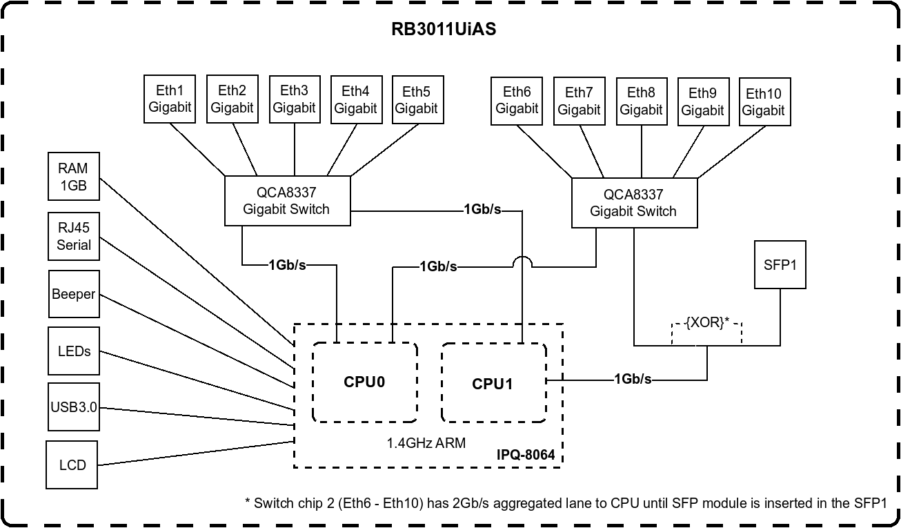
The physical ports are connected via switch chips to the CPU and use port-based VLANs (not 802.1Q) to multiplex the individual port traffic to logical interfaces presented in the UI / CLI, so:
eth10 socket -> switch chip #2 -> switch2-cpu interface -> ethernet driver -> logical ether10 interface
You can configure bridges, ports and VLANs in numerous ways due to the flexibility afforded by RouterOS, howver being able to configure something doesn't make it correct - here are various pitfalls https://help.mikrotik.com/docs/display/ ... figuration. Multiple bridges are also not recommended as hardware switching between switch ports is disabled on all but the first bridge, although this may not be an issue in your particular scenario.
When you connect to ether10, and have the default route on your computer set to 10.0.0.1/24, then addresses on any other interface can be used to access the Mikrotik unless you have firewall rules to prevent it as the default input/forward/output policy is accept, not drop. As with any linux-based system addresses on any interface are reached via the input chain, not the forward chain despite being in different subnets, this is occurring at L3.
Re: Management interface and general logic behind interfaces
Hi tdw, and thanks for your reply.
Well, what I meant by “Out-Of-Band” is a independent Network port which is hard-wired for management only can cannot be used for something else (e.g. routing or traffic processing). I admit that for most scenarios this means “wasting” a port for management only, but in some critical deployments this is pf utmost importance (I’ve worked on MIL/GOV projects where such ports were mandatory for the project. Devices without this capacity were disqualified from the beginning).
I admit, a dedicated management VLAN (over a dedicated VRF if possible) is an acceptable compromise in most deployments - including mine.
According to your explanation (“eth10 socket -> switch chip #2 -> switch2-cpu interface -> ethernet driver -> logical ether10 interface”), this means that switched (not routed!) traffic from any port of switch 1 needs to go through the ASIC of SW1, then the ASIC of SW2 to get to a port of SW2. Therefore, in a high-traffic pair of ports should be keps on the same switch rather than split over both switches. Is that Correct?
From my understanding, this is somewhat different from switches were all ports are connected to a bus on the backplane whose max bandwidth is the half of the all port’s BW.
But on the other hand, the 3011 is definitely meant to be used as a router, so this “limitiation” is irrelevant, the traffic being processed by the CPU anyway in that case.
My initial config with individual bridges was definitely not a good option. This was more to play with it and see how it behaved.
In my scenario, I thing the best is to simply have the L3 directly mapped to each physical interface.
Your comment regarding the interface behaviour (the fact that the Mikrotik responds to the IP assigned to eth10 on ALL interfaces) is very interesting. But doesn’t that imply that all interfaces are switched with a sort of common uplink to the L3?
If so, that would mean that all devices connected on the mikrotik are able to communicate with each other on L2, which I see as a very bad thing. For instance, if you have a WAN and LAN segment that would share the same L2 broadcast domain and only be separated by their L3 addressing plan.
If this is the case, the only way I see to avoid this would be to assign a different VLAN to each single port.
(I am still not done reading the excellent link you sent me, I think some of my questions will already be answered there. I’ll keep you posted)
Cheers
Denis
Re: Management interface and general logic behind interfaces
OK, so dedicated ethernet rather than some other interface technology (USB, serial, etc.)Well, what I meant by “Out-Of-Band” is a independent Network port which is hard-wired for management only can cannot be used for something else (e.g. routing or traffic processing).
Abusing routing filters to insert the route into another table, rather than VRF would work too. Or just IP firewall filters.I admit, a dedicated management VLAN (over a dedicated VRF if possible) is an acceptable compromise in most deployments - including mine.
Yes, it is actually worse than that as inter-switch traffic passes through CPU interfaces - see https://i.mt.lv/cdn/product_files/RB301 ... 160313.png. The RBxxxx devices with more than five ethernet ports all have this style of port expansion, as you say primarily intended to be a router rather than a switch. The CRSxxx have a more conventional wirespeed switch architecture plus a small CPU to provide some additional services, but not approaching anything like wirespeed.According to your explanation (“eth10 socket -> switch chip #2 -> switch2-cpu interface -> ethernet driver -> logical ether10 interface”), this means that switched (not routed!) traffic from any port of switch 1 needs to go through the ASIC of SW1, then the ASIC of SW2 to get to a port of SW2. Therefore, in a high-traffic pair of ports should be keps on the same switch rather than split over both switches. Is that Correct?
From my understanding, this is somewhat different from switches were all ports are connected to a bus on the backplane whose max bandwidth is the half of the all port’s BW.
But on the other hand, the 3011 is definitely meant to be used as a router, so this “limitiation” is irrelevant, the traffic being processed by the CPU anyway in that case.
There are various limititations/pitfalls, other than the CRS3xx devices having a vlan-aware bridge disables hardware switching so all of the physical port traffic is multiplexed back over the internal links to the CPU. It is possible to use a non-vlan-aware bridge, which behaves like an unmanaged switch, and then configure the switching directly. There are some additional caveats on devices with multiple switch chips as mentioned in one section of the link sent previously.My initial config with individual bridges was definitely not a good option. This was more to play with it and see how it behaved.
In my scenario, I thing the best is to simply have the L3 directly mapped to each physical interface.
No. Using your example of eth9: 192.168.88.1/24 and eth10: 10.0.0.1/24 with no bridges, i.e. the addresses attached directly to the ports each in a L2 domain. If you have a device attached to eth10 with an address of 10.0.0.99/24 and a default gateway of 10.0.0.1 and ping 192.168.88.1 the device will forward the packet to 10.0.0.1 as it is not directly reachable. Despite being in a different subnet this is handled via the L3 input chain on the Mikrotik, not the L3 forward chain. The packet flow is described here https://help.mikrotik.com/docs/display/ ... n+RouterOSYour comment regarding the interface behaviour (the fact that the Mikrotik responds to the IP assigned to eth10 on ALL interfaces) is very interesting. But doesn’t that imply that all interfaces are switched with a sort of common uplink to the L3?
If so, that would mean that all devices connected on the mikrotik are able to communicate with each other on L2, which I see as a very bad thing. For instance, if you have a WAN and LAN segment that would share the same L2 broadcast domain and only be separated by their L3 addressing plan.