
Redundant PoE Power
Is anyone using a redundant PoE setup? I have two AC power sources that are far apart from each other. I would like to power a single routerboard with both power sources using POE. I am thinking of a 12-24v DC switch that I can inject 2 inputs and a single output. I know APC makes them for AC but not sure where to find a DC one.

Re: Redundant PoE Power
Actually, if I'm not totally wrong, all UPS-devices are AC which is then "converted" to DC with a huge powerloss as a result 
Edit: sorry for off topic!
Edit: sorry for off topic!
Re: Redundant PoE Power
Probably too expensive for just one device, but this PDU has redundant power option. Plus you can on/off each outlet remotely.
PDUMH15ATNET
PDUMH15ATNET
Re: Redundant PoE Power
By the way, if it is a 450G I know that it has a second power supply on the mainboard inside of the device so you can go all nuts and have 3 powersupplies!
-

-
TomjNorthIdaho
Forum Guru

- Posts: 1493
- Joined:
- Location: North Idaho
- Contact:
Re: Redundant PoE Power
Redundant power to a Mikrotik RB is not a bad idea.Is anyone using a redundant PoE setup? I have two AC power sources that are far apart from each other. I would like to power a single routerboard with both power sources using POE. I am thinking of a 12-24v DC switch that I can inject 2 inputs and a single output. I know APC makes them for AC but not sure where to find a DC one.
You might be able to do it this way:
Ethernet0 - use your normal POE injector
Ethernet1 - use a Y splitter where you gain the little 12-volt power cord and connect the 12-volts into the power port. (or use a 12 volt splitter)
Bridge E0 and E1 (if you also want to have redundant Ethernet data)
This just might be able to keep a Mikrotik running if you cut one of the two ethernet cables to your Mikrotik.
Re: Redundant PoE Power
basically i have the two AC outlets, but they are hundreds of feet apart. Id like to use PoE injectors at both locations to run about 150-200 feet to where they meet have a poe injector that could accept 2 inputs and a single output (to eth1). i know if I had exactly the same voltage level at both I could use some diodes to prevent backpressure, but wanted something a little more industrial. I think what I am looking for would be a DC switch, when one is present it uses it, when it dies the second one kicks in within nanoseconds (or however fast it needs to keep things up).
im not worried about the ethernet piece, i can handle that by using cat5 with only poe and split things as needed.
im not worried about the ethernet piece, i can handle that by using cat5 with only poe and split things as needed.
-

-
roc-noc.com
Forum Veteran

- Posts: 874
- Joined:
- Location: Rockford, IL USA
- Contact:
Re: Redundant PoE Power
You need a two position DC relay to isolate the two power supplies. It should be powered by one of the supplies. If that supply dies the relay goes the other way and the other POE input is supplying power.
But is this really needed?
Good quality switching power supplies are very reliable.
Tom
But is this really needed?
Good quality switching power supplies are very reliable.
Tom
Re: Redundant PoE Power
But I have two different power sources, 120V from one house, and another from a deep cycle battery being charged by another houses AC. Good idea on the relay. I didnt think about that.Good quality switching power supplies are very reliable.

Re: Redundant PoE Power
Check out http://tyconpower.com/products/POE.htm They have DC to DC POEs and they support two power inputs.

Re: Redundant PoE Power
Redundant PoE Power can build their own hands - http://tandem.ck.ua/ups_mt-eng.phpIs anyone using a redundant PoE setup? I have two AC power sources that are far apart from each other. I would like to power a single routerboard with both power sources using POE. I am thinking of a 12-24v DC switch that I can inject 2 inputs and a single output. I know APC makes them for AC but not sure where to find a DC one.
We made them more than 60 pieces.
Pay attention to the UPS-MT-monitor - http://tandem.ck.ua/ups_mtm-eng.php
Last edited by matrot2 on Tue Dec 07, 2010 10:54 pm, edited 1 time in total.
Re: Redundant PoE Power
Were are the pics on the site. Fix them!Redundant PoE Power can build their own hands - http://tandem.ck.ua/ups_mt-eng.php/Is anyone using a redundant PoE setup? I have two AC power sources that are far apart from each other. I would like to power a single routerboard with both power sources using POE. I am thinking of a 12-24v DC switch that I can inject 2 inputs and a single output. I know APC makes them for AC but not sure where to find a DC one.
We made them more than 60 pieces.
Pay attention to the UPS-MT-monitor - http://tandem.ck.ua/ups_mtm-eng.php
Re: Redundant PoE Power
Sorry.Were are the pics on the site. Fix them!Redundant PoE Power can build their own hands - http://tandem.ck.ua/ups_mt-eng.php/Is anyone using a redundant PoE setup? I have two AC power sources that are far apart from each other. I would like to power a single routerboard with both power sources using POE. I am thinking of a 12-24v DC switch that I can inject 2 inputs and a single output. I know APC makes them for AC but not sure where to find a DC one.
We made them more than 60 pieces.
Pay attention to the UPS-MT-monitor - http://tandem.ck.ua/ups_mtm-eng.php
Redundant PoE Power can build their own hands - http://tandem.ck.ua/ups_mt-eng.php
Re: Redundant PoE Power
hi,
you can use this: http://www.restlesspowerbox.com
Compact is a very nice small devic with managment over lan or by mobilephone with SMS
you can use this: http://www.restlesspowerbox.com
Compact is a very nice small devic with managment over lan or by mobilephone with SMS
Re: Redundant PoE Power
i could use that, but its 680$ too much : ) its also way too large for what I need. thanks though.
Re: Redundant PoE Power
These will take two DC inputs and switch the active one to the output:
-

-
marcosvelez
Trainer

- Posts: 4
- Joined:
Re: Redundant PoE Power
Is very simple to develop a poe of redundancy in power,
you need to have two DC
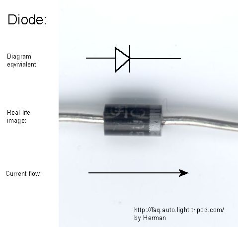
and two diodes for DC, its function in this application is to determine of the flow direction tension.
you will put an diode on each power injector, the output voltage or the positive.
the connection is as follows:
Power 1 dc (diode) power direction conect this two powers
----------vcc(+) ->| -------- vcc(+) ------------
Power 2 dc | ------------- vcc redundancy Routerboard
----------vcc(+) ->| --------- vcc(+) ------------
(anodes) (cathodes)
conect Power 1 and Power 2 ground(-) ====================== ground redundancy Routerboard
Notes: its two power injectors has to be the same voltage and current (example: 12V 2A)
note2:tension will not go the opposite direction in the circuit so the source will not burn
note3: the current is the sum of the two sources while your two are enabled but the current consumption will be just what the Routerboard require, if one source fails, the other is already on.
note4: this image has explicate the simbol (->|)
note5: diodes are several amps, look for a 50% higher than its implementation,
example is the source of its 2A diode should be 3A
But if what you seek is redundancy batteries using the tip above is very good.
you need to have two DC
and two diodes for DC, its function in this application is to determine of the flow direction tension.
you will put an diode on each power injector, the output voltage or the positive.
the connection is as follows:
Power 1 dc (diode) power direction conect this two powers
----------vcc(+) ->| -------- vcc(+) ------------
Power 2 dc | ------------- vcc redundancy Routerboard
----------vcc(+) ->| --------- vcc(+) ------------
(anodes) (cathodes)
conect Power 1 and Power 2 ground(-) ====================== ground redundancy Routerboard
Notes: its two power injectors has to be the same voltage and current (example: 12V 2A)
note2:tension will not go the opposite direction in the circuit so the source will not burn
note3: the current is the sum of the two sources while your two are enabled but the current consumption will be just what the Routerboard require, if one source fails, the other is already on.
note4: this image has explicate the simbol (->|)
note5: diodes are several amps, look for a 50% higher than its implementation,
example is the source of its 2A diode should be 3A
But if what you seek is redundancy batteries using the tip above is very good.
Who is online
Users browsing this forum: No registered users and 42 guests