I have a question about MIMO1 and MIMO2 entry of CHATEAU LTE12
When connecting external antenna on it, the signal is like non antenna are connected.
Is this normal ?
I was thinking that connecting antenna on it will have the same signal while connecting on MAIN or DIV Antenna but seems not
Thanks for light on this.
Maybe I didn’t connect correctly ?
This is what I have done to use both antenna and both mimo2.
The idea is to set external antenna to NONE to set CHATEAU to use all internal, except here, I did connect all internal (MAIN/DIV/MIMO) to four external connector :
This give that :
Like this, setting CHATEAU to NONE, will not emit any 4G wave (the router is near me) and all 4G will use external antenna but if I’m letting only connected ANT2 and ANT3.
We can clearly see that performance are not good like no antenna connected
PS : Reboot done ofc
EDIT : Led indicate no signal and internet is very low and after few seconds, no more internet !!!
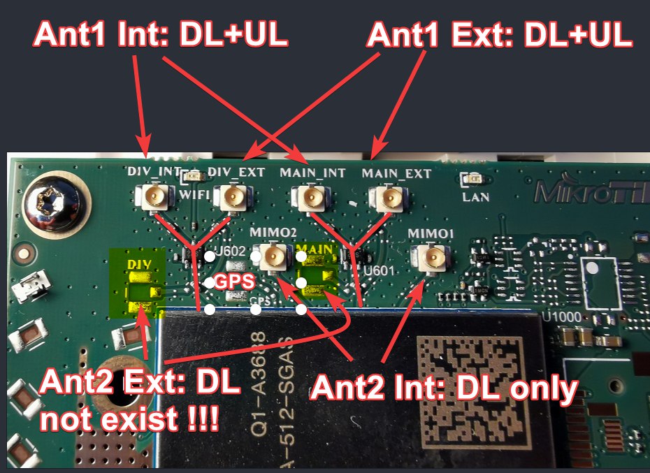
There are total 4 antenna connections for the CAT12 modem
means, 2x antenna with mimo 2x2, but in specification and brochure of Quectel SoC we see “Mimo 2x2,4x2” who give us info about that 4 connectors are
[]1st antenna (2 connectors): 1pair for DL+UL what give 2x2 as internal and external
[]2nd antenna (2 connectors): 1 pair for DL only to create 4x2 but I think only with “internal setup” bcs with external that antenna will be not used ?! and that why you reach -140 ?? By testing only you can confirm that stuff. Remember that 2nd antenna not have pigtail to outside of chateau.
Chateau have got EG12-EA soldered at PCB and that 2nd internal antenna must be always set as internal and to use your own antenna you must unplug ipex from PCB and install own pigtail with still internal settings - because I not see at photos the empty connectors at PCB, they not should be exist. and setting the second one as external you just disable it.
and for 2 antenna connections you can change from internal to external antenna
means like we can change int/ext for both antennas
you can configure both antennas connectors separately (which will be external and which internal).
again, means like we can change int/ext for both antennas
For the TX only the main (first) antenna is used - which can be configured to external.
Tx=UL=upload is done only at main, 1st antenna.
That I read this answer.
system/routerboard/modem/set main-antenna= auto external internal
[admin@MikroTik] > system/routerboard/modem/set diversity-antenna= auto external internal
[admin@MikroTik] > system/reboot ;
Seams like main-antenna is for DL+UL but second antenna know as diversity-antenna was always as DL antenna. And we not receive info about reboot needed but I have one person who confirm that only after reboot he see changes in signals.
I hope that can help you in anythink, maybe I just write obvious stuff and this is just empty post.
Thanks SiB,
I’m trying to understand what you explain
I have pigtail/SMA for ANT2 and ANT3 possibility, now just to figure out how to plug it and with correct settings to be usefull.
[]1st antenna (2 connectors): 1 pair for DL+UL what give 2x2 as internal and external
[]2nd antenna (2 connectors): 1 pair for DL only to create 4x2 but I think only with “internal setup” bcs with external that antenna will be not used ?! and that why you reach -140 ?? By testing only you can confirm that stuff. Remember that 2nd antenna not have pigtail to outside of chateau.
Chateau have got EG12-EA soldered at PCB and that 2nd internal antenna must be always set as internal and to use your own antenna you must unplug ipex from PCB and install own pigtail with still internal settings - because I not see at photos the empty connectors at PCB, they not should be exist. and setting the second one as external you just disable it.
I don’t really understand this part
For me, one connector from motherboard (for example MAINT_EXT) is composed with 2 wired (PLUS the receiver and GND) this means 1 antenna.
So each connector = one antenna.
.
That I read this answer.
Ok, I’m pretty sure you are right but you lost me
.
system/routerboard/modem/set main-antenna= auto external internal
[admin@MikroTik] > system/routerboard/modem/set diversity-antenna= auto > external > internal
[admin@MikroTik] > system/reboot ;
.
Seams like main-antenna is for DL+UL but second antenna know as diversity-antenna was always as DL antenna. And we not receive info about reboot needed but I have one person who confirm that only after reboot he see changes in signals.
It seems that reboot is not needed anymore but I can’t confirm this, at least I always set a setting and reboot and get the same result as when before rebooting.
.
I hope that can help you in anythink, maybe I just write obvious stuff and this is just empty post.
Thanks
.
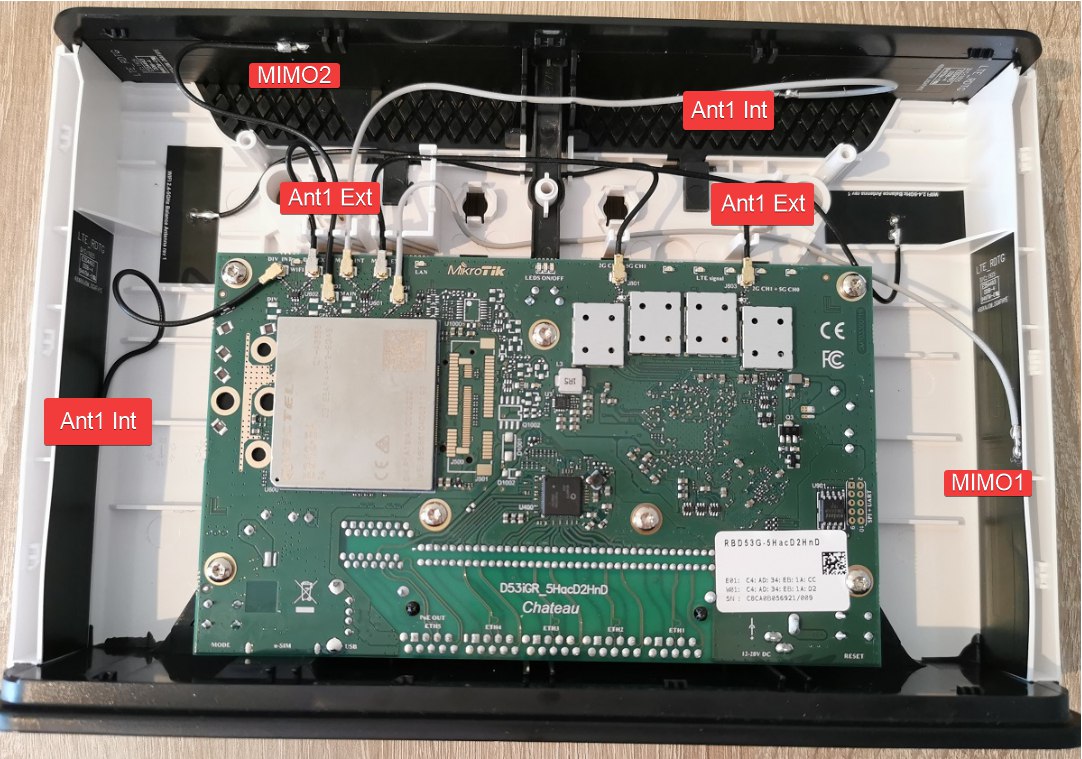
On board like seen in above photos, we have as 6 LTE connectors :
MAIN_INT
DIV_INT
MAIN_EXT
DIV_EXT
MIMO1
MIMO2
So in theory, we can connect 6 antennas, so based on normal configuration, MIMO1 and MIMO2 (are internal antenna) and should work only with internal antenna (MAIN_INT and DIV_INT) and I don’t think it works when MAINT_EXT and DIV_EXT are set.
So from what I have tested, connecting only pigtail/SMA on MIMO1 and MIMO2 so using external antenna to get best signal (-80db for me), what ever the setting used, Auto/Both/Main/Div/None (each reboot between change), I’m not getting any signal !
I think they are connected like that:
What give you info that Ant1 and Mimo are H and V with 90° angle.
This mean the Ant2 Ext , even if you configure it at ROS, going to not soldered u.FL (not existing in Chateau) connectors, when you select the second antenna as external then you always receive NO SIGNAL.
GPS socket is not soldered to PCB too, no way to connect it even if EG12-EA support it. Means GPS have no signal bcs no antenna.
So this means in the current hardware, the best will be to connect
MAIN/DIV (INT) ANTENNA1 to the external SMA (original)
MIMO1 and MIMO2 ANTENNA2 to new external SMA (need to be mounted on rear panel)
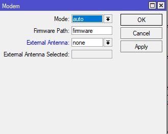
And setup Mikrotik as using INTERNAL ANTENNA :
In Modem setting, put “none” in External Antenna configuration.
In this configuration the value returned by this command gives :
The modem supports 6 spatial streams, so it works like this:
For 1 CA single band 4x4 mimo = 4 streams.
For 2 CA primary band 4x4 mimo + secondary 2x2 mimo = 6 streams
For 3 CA all 3 bands use 2x2 mimo = 6 streams
Modem uses the mimo1 and mimo2 antenna only when operating in 4x4.
The last 2 values of AT+QRSRP should return the levels of the mimo1 and mimo2 or -140 if not used.
But keep in mind that only main antenna is used for Tx and Rx the rest are only for Rx.
So 4x4 MIMO is supported only up to 2 CA for the EG12 modem.
Also 4x4 MIMO is supported only for LTE-FDD: B1/B3/B7.
so to understand..I would like to attach my panel antenna with two SMA connector to the chateau.
do I have to attach them to ANT1 and ANT4..correct?
then, how should I configure with winbox?
OK so disconnect MIMO1 and MIMO2 and put there uFL pigtails ↔ SMA, then connect another antenna.
Currently using 2 x ATK504 (45 degrees) I’ve got:
output: +QRSRP: -102,-104,-140,-140
This gives me B3 as primary band and B1+B20 as CA, so 3 CA working fine 60-120 Mbit depends on time of day, RSSI is ~ 75 dBm, RSRP (for B3) is 99-102 dBm (86-88 for B20), wondering if I can get anything more with that - got another not used antenna - Cybertech 1800-2100 that I can use anytime just neet to shorten cables and buy uFL pigtails.
-140 means that is not work now, you can try download some stuff to generate traffic and check that in loop to see if it’s activated.
system/routerboard/modem/set diversity-antenna=
auto external internal ← select internal
[admin@MikroTik] > system/reboot ;
MIMO4x4 works only when you have B3+1+7