Heya there, I can not Access my Switch via a “VLAN IP”, only via “LAN IP”.
My setup:
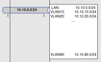
Fritzbox ISP → opnsense router/firewall → CRS326 → Clients
I have two WAN, one LAN and several VLANs configured in the opnsense router. I can access everything quite fine, everything is working as expected, with one exception: I cannot access the switch itself from any VLAN, I can only access it via LAN. It does not seem to be an issue within opnsense, as the problem occurs even if I switch Firewall Rules completely off. I can also access any other “client” or “server” from VLANs to LAN (if the rules are setup accordingly or are disabled), so basically it is working.
I have given the switch several IPs in the respective Networks, and I can only acces it via LAN, I can not access any IP beside the “LAN” one (which means without VLAN tag). What do I miss?
It is unlikely, that anyone will be able to help you with anything, if you do not publish a backup copy of your switch settings in text form. By removing all non-public information from this backup.
Are you using RouterOS or SwitchOS in your CRS326? Which version of whichever one you are using. For the moment, I am going to assume RouterOS. If that is the case, please export and post your configuration. To export and paste your configuration (and I’m assuming you are using WebFig or Winbox), open a terminal window, and type (without the quotes) “/export hide-sensitive file=any-filename-you-wish”. Then open the files section and right click on the filename you created and select download in order to download the file to your computer. It will be a text file with whatever name you saved to with an extension of .rsc. Suggest you then open the .rsc file in your favorite text editor and redact any sensitive information. Then in your message here, click the code display icon in the toolbar above the text entry (the code display icon is the 7th one from the left and looks like a square with a blob in the middle). Then paste the text from the file in between the two code words in brackets.
If you are using SwitchOS, configuration is completely different so we’ll ask a different way of telling us how it is configured.
take a look at this
Switch Management Access Configuration
Good Morning!
First of all, thanks for helping a newbie - highly appreciated!
Apologies for not providing the necessary information, I have attached the switch config:
CRS328_20220730_1028_clean.rsc (6.37 KB)
I have also added a crude draw.io made picture of my network assets, quite simplified:
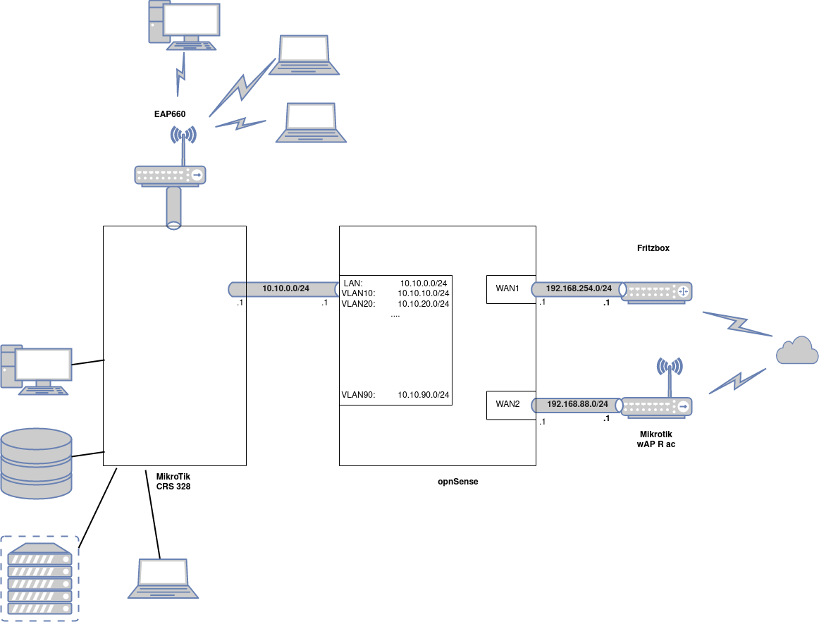
Please note that everything in my setup is working as expected, with the sole exception of accessing the switch from within the VLANs. I can access is without VLAN-Tag from LAN without any hassle.
This did not bother me until I started actually USING the VLANs, meaning: putting devices into seperate networks where the devices can for example not access the internet freely - my monitoring server is within a VLAN, and I’d love to be able to access the switch from it, otherwise it would be quite senseless.
If you need more information I will provide gladly, thank you for your help.
Maybe I’m wrong, but you may add “bridge” interface as “tagged”. As example:
/interface bridge vlan add bridge=bridge1 tagged=bridge1,ether1 untagged=ether2 vlan-ids=19
One more thing. As far as I understand, you connect some ports with MTU 9000. IMHO, you need to increase L2MTU while doing this. Example:
/interface ethernet set [ find default-name=ether10 ] l2mtu=9092 mtu=9000
So, after making my post and providing the basics I then continued with working what you have advised me so far.
I tried all three of those advices given in the documentation, neither of those worked:
Which makes me wonder that there must be something else I am missing.
Will try and report immediately, sir!
Ya, this ports are connected directly via fibre to a NAS and a workstation. Obv I was wrong in just putting both MTUs to 9000, obv I failed. Will fix this, thank you!
So I tried what you said, but this failed, what is not a big suprise as this is like the version “Tagged access without VLAN filtering” from
https://help.mikrotik.com/docs/display/ROS/Bridging+and+Switching#BridgingandSwitching-Managementaccessconfiguration
There must be something different or faulty in my setup. I just have no clue what it is. And I have such a simple use case - I mean it can’t be that hard to access the IP of the switch from within the VLAN which is routed through the switch, dammit. Sorry for swearing… ![]()
Do you have route on switch to vlan networks?
I did not add any routes on the switch itself, as I use my opnsense for routing purposes, but this is definately something with which I am struggling. A lot!
Where can I check if there is a route, what should I add?
So my TLDR answer: I don’t think so…
Please, write the name of the interface (port in the switch), that connects this switch to the router. That is, which port is uplinked.
This would be ether23_opnsense1.
Sometimes. a big problem is to deal with the settings that are made through QuickSet. I don’t like, it when I don’t understand how it works. Or how it doesn’t work.
So, let’s look at the configuration file.
/interface bridge name=bridge vlan-filtering=yes
We have a bridge, on which filtering is performed.
We will follow the simplest path, we have all the ports or “trunk” or “access”.
We look in the documentation - https://help.mikrotik.com/docs/display/ROS/Bridging+and+Switching#BridgingandSwitching-VLANExample-TrunkandAccessPorts
And we’ll look at the diagram, that you drew.
To be honest - I don’t like that you have VLAN, but there is just a local area network. Rather, it is also VLAN with PVID 1. From my point of view, it would be easier to deal with the configuration if all networks were with VLAN.
Suppose, we select VLAN 99 for the local network. In this case, the classic configuration view would look like this:
/interface vlan
add interface=bridge name=VLAN_10 vlan-id=10
add interface=bridge name=VLAN_20 vlan-id=20
add interface=bridge name=VLAN_30 vlan-id=30
add interface=bridge name=VLAN_40 vlan-id=40
add interface=bridge name=VLAN_50 vlan-id=50
add interface=bridge name=VLAN_60 vlan-id=60
add interface=bridge name=VLAN_70 vlan-id=70
add interface=bridge name=VLAN_80 vlan-id=80
add interface=bridge name=VLAN_90 vlan-id=90
add interface=bridge name=VLAN_99 vlan-id=99
Now we need to understand, where to send and where to receive tagged and untagged traffic.
Tagged ports:
/interface bridge port
add bridge=bridge interface=ether23_opnsense1
add bridge=bridge interface=ether24_opnsense2
add bridge=bridge interface=Syno_Bond
add bridge=bridge interface=sfp-sfpplus1_wifi
add bridge=bridge interface=sfp-sfpplus3_proxmox
Unagged ports for VLAN10:
/interface bridge port
add bridge=bridge interface=ether1_edgebox pvid=10
add bridge=bridge interface=ether2_nosbox pvid=10
add bridge=bridge interface=ether3_IPMI-edgebox pvid=10
Untagged ports for the current local network 10.10.0.0/24:
/interface bridge port
add bridge=bridge interface=ether4_Test-black pvid=99
add bridge=bridge interface=ether5_piBlack pvid=99
add bridge=bridge interface=ether6 pvid=99
add bridge=bridge interface=ether7 pvid=99
add bridge=bridge interface=ether8 pvid=99
add bridge=bridge interface=ether9 pvid=99
add bridge=bridge interface=ether10 pvid=99
add bridge=bridge interface=ether11 pvid=99
add bridge=bridge interface=ether12 pvid=99
add bridge=bridge interface=ether13 pvid=99
add bridge=bridge interface=ether14 pvid=99
add bridge=bridge interface=ether16_BRIDGE2! pvid=99
add bridge=bridge interface=ether17_IPMI-proxmox pvid=99
add bridge=bridge interface=ether18_OS-Laptop pvid=99
add bridge=bridge interface=ether19_CCU3 pvid=99
add bridge=bridge interface=ether20 pvid=99
add bridge=bridge interface=sfp-sfpplus2_neuromancer pvid=99
add bridge=bridge interface=sfp-sfpplus4_truenas pvid=99
I can be wrong - therefore, you will correct the exact name of the ports, to which the necessary VLAN traffic should be sent.
And finally:
/interface bridge vlan
add bridge=bridge tagged="ether23_opnsense1,ether24_opnsense2,sfp-sfpplus3_proxmox,sfp-sfpplus1_wifi,Syno_Bond,bridge" untagged=ether2_nosbox,ether3_IPMI-edgebox,ether1_edgebox vlan-ids=10
add bridge=bridge tagged="ether23_opnsense1,ether24_opnsense2,sfp-sfpplus3_proxmox,sfp-sfpplus1_wifi,bridge" vlan-ids=20
add bridge=bridge tagged="ether23_opnsense1,ether24_opnsense2,sfp-sfpplus3_proxmox,sfp-sfpplus1_wifi,bridge" vlan-ids=30
add bridge=bridge tagged="ether23_opnsense1,ether24_opnsense2,sfp-sfpplus3_proxmox,sfp-sfpplus1_wifi,bridge" vlan-ids=40
add bridge=bridge tagged="ether23_opnsense1,ether24_opnsense2,sfp-sfpplus3_proxmox,sfp-sfpplus1_wifi,bridge" vlan-ids=50
add bridge=bridge tagged="ether23_opnsense1,ether24_opnsense2,sfp-sfpplus3_proxmox,sfp-sfpplus1_wifi,bridge" vlan-ids=60
add bridge=bridge tagged="ether23_opnsense1,ether24_opnsense2,sfp-sfpplus3_proxmox,sfp-sfpplus1_wifi,bridge" vlan-ids=70
add bridge=bridge tagged="ether23_opnsense1,ether24_opnsense2,sfp-sfpplus3_proxmox,sfp-sfpplus1_wifi,bridge" vlan-ids=80
add bridge=bridge tagged="ether23_opnsense1,ether24_opnsense2,sfp-sfpplus3_proxmox,sfp-sfpplus1_wifi,bridge" vlan-ids=90
add bridge=bridge tagged="ether23_opnsense1,ether24_opnsense2,sfp-sfpplus3_proxmox,sfp-sfpplus1_wifi,bridge" untagged=ether4_Test-black,ether5_piBlack,ether6,ether7,ether8,ether9,ether10,ether11,ether12,ether13,ether14,ether16_BRIDGE2!,ether17_IPMI-proxmox,ether18_OS-Laptop,ether19_CCU3,ether20,sfp-sfpplus2_neuromancer,sfp-sfpplus4_truenas vlan-ids=99
The current option that I described does not exclude access from VLAN with PVID 1.
The spelling for “CRS3xx, CRS5xx series switches, CCR2116, CCR2216 and RTL8367, 88E6393X, 88E6191X and MT7621 switch chips” will be slightly different from this. In any case, you need to understand exactly which switch ports are responsible for what. And what kind of traffic should be sent there.
/interface bridge vlan
add bridge=bridge tagged="bridge,ether24_opnsense2,ether23_opnsense1,ether21_SynoBond\
    1,sfp-sfpplus3_proxmox,sfp-sfpplus1_wifi" untagged=\
    ether2_nosbox,ether3_IPMI-edgebox,ether1_edgebox vlan-ids=10
add bridge=bridge tagged="bridge,ether24_opnsense2,ether23_opnsense1,sfp-sfpplus3_pro\
    xmox,sfp-sfpplus1_wifi" vlan-ids=90
add bridge=bridge tagged="bridge,ether23_opnsense1,ether24_opnsense2,sfp-sfpplus3_pro\
    xmox,sfp-sfpplus1_wifi" vlan-ids=20
add bridge=bridge tagged="bridge,ether23_opnsense1,ether24_opnsense2,sfp-sfpplus3_pro\
    xmox,sfp-sfpplus1_wifi" vlan-ids=30
add bridge=bridge tagged="bridge,ether23_opnsense1,ether24_opnsense2,sfp-sfpplus3_pro\
    xmox,sfp-sfpplus1_wifi" vlan-ids=40
add bridge=bridge tagged="bridge,ether23_opnsense1,ether24_opnsense2,sfp-sfpplus3_pro\
    xmox,sfp-sfpplus1_wifi" vlan-ids=50
add bridge=bridge tagged="bridge,ether23_opnsense1,ether24_opnsense2,sfp-sfpplus3_pro\
    xmox,sfp-sfpplus1_wifi" vlan-ids=60
add bridge=bridge tagged="bridge,ether23_opnsense1,ether24_opnsense2,sfp-sfpplus3_pro\
    xmox,sfp-sfpplus1_wifi" vlan-ids=70
add bridge=bridge tagged="bridge,ether23_opnsense1,ether24_opnsense2,sfp-sfpplus3_pro\
    xmox,sfp-sfpplus1_wifi" vlan-ids=80
Some errors. ether21_SynoBond1 is a part of Syno_Bond
First of all: Thank you very much for your help!
But, thing is: I don’t want to change everything just to get access from a single VLAN to my switch. It just confuses that I should completely overhaul my setup, which is working fine beside the missing access to the switch. I’d rather put my Monitoring server on LAN / pvid1 then. Thing is: I wanted to keep pvid1 / LAN / non VLAN traffic, exactly because it is just that: transparent ethernet traffic as base.
Question is: what’s wrong with my setup that this access does not work? What is solved with your approach? can’t we combine it to achieve my goal “access to the switch from vlan”?
@akakua: My you enlighten me what your approach would be? What is different from my current setup? Will fiddle around with it a bit, but a bit of context would be great - if I am not asking too much, that is. Don’t wanna be rude or something, glad you’ll try to help me!
So nobody an idea why I cannot access the switch? Or enlighten me further? What akakua has suggested is already implemented, like being part of my network already…
Is the config you posted still accurate?
If so, can you explain the purpose of bridge2? That isn’t normally recommended when using the “new way” of vlans. Instead of creating more than one bridge, you should put everything into the same bridge. Think of each bridge as a separate virtual switch. I don’t understand enough about the implications to know if that’s causing a problem or not.
But the thing that does “pop out” as a problem is that you don’t have any connection from the ports to the the bridge i.e. the “CPU’s connection to the switch”. Both @BrateloSlava in post #13 and @akakua in post #14 have included the bridge device (in different positions in the line) in the /interface bridge vlan stanza, but perhaps you didn’t notice what they were referring to (it can be hard to see things when you don’t know what the different part is, and unless you use a differences tool).
I.e. your configuration is missing the parts in red. And can you explain what the purpose of the green part is?
/interface bridge
add admin-mac=08:55:31:94:90:13 auto-mac=no comment=defconf name=bridge
vlan-filtering=yes
add name=bridge2
/interface bridge vlan
add bridge=bridge tagged=“**bridge,**ether24_opnsense2,ether23_opnsense1,ether21_SynoBond
1,sfp-sfpplus3_proxmox,sfp-sfpplus1_wifi” untagged=
ether2_nosbox,ether3_IPMI-edgebox,ether1_edgebox vlan-ids=10
add bridge=bridge tagged=“**bridge,**ether24_opnsense2,ether23_opnsense1,sfp-sfpplus3_pro
xmox,sfp-sfpplus1_wifi” vlan-ids=90
add bridge=bridge tagged=“**bridge,**ether23_opnsense1,ether24_opnsense2,sfp-sfpplus3_pro
xmox,sfp-sfpplus1_wifi” vlan-ids=20
add bridge=bridge tagged=“**bridge,**ether23_opnsense1,ether24_opnsense2,sfp-sfpplus3_pro
xmox,sfp-sfpplus1_wifi” vlan-ids=30
add bridge=bridge tagged=“**bridge,**ether23_opnsense1,ether24_opnsense2,sfp-sfpplus3_pro
xmox,sfp-sfpplus1_wifi” vlan-ids=40
add bridge=bridge tagged=“**bridge,**ether23_opnsense1,ether24_opnsense2,sfp-sfpplus3_pro
xmox,sfp-sfpplus1_wifi” vlan-ids=50
add bridge=bridge tagged=“**bridge,**ether23_opnsense1,ether24_opnsense2,sfp-sfpplus3_pro
xmox,sfp-sfpplus1_wifi” vlan-ids=60
add bridge=bridge tagged=“**bridge,**ether23_opnsense1,ether24_opnsense2,sfp-sfpplus3_pro
xmox,sfp-sfpplus1_wifi” vlan-ids=70
add bridge=bridge tagged=“**bridge,**ether23_opnsense1,ether24_opnsense2,sfp-sfpplus3_pro
xmox,sfp-sfpplus1_wifi” vlan-ids=80
add bridge=bridge2 tagged=bridge2,VLAN_50 vlan-ids=50
First of all: Back from vacation, sorry for my late reply!
Second: Thanks for enlighten me further, highly appreciated!
Regarding the bridge2: That is a relic of me tinkering around to get this working (hence it was only attached to vlan50). I removed it, because it solves no function, should have done that immediately after the test, sorry for that.
Regarding the tagging of the bridge itself: Winbox does not let me do that, don’t know why. The options are greyed out:
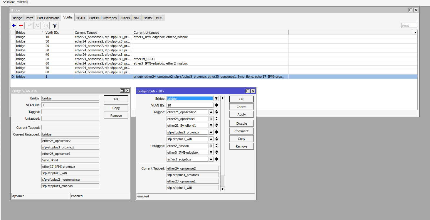
I did all my configuration via winbox - under the assumption that everything can be done either via the terminal or via winbox/webview - was that assumption incorrect? Or am i missing something else here? My config has not change much beside the removal of bridge2, I have attached the current config.
Can I simply put the commands into the console and they are “overwrting” the current bridge settings? I am scared a bit about completely losing my config…
O, and btw, I almost forgot to mention:
What @BrateloSlava in post #13 and @akakua in post #14 have included was actually NOT noticed by me, sorry for that - I just didn’t read carefully enough, sorry ![]()
CRS328_20220814_1125.rsc (6.26 KB)
So, a new post to document my stupidness - sorry for the doublepost, but please be so kind and ignore everything in the post above. I was just doing it wrong - you tag the bridge in the respective VLAN. Done just that end HEUREKA its working…