Assistance Needed with MikroTik Cloud Router Configuration

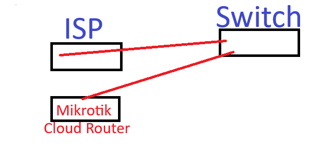
Hello. I’m encountering an issue with a MikroTik Cloud Router and would appreciate some assistance. The setup involves an ISP router that connects to a switch, and from there, we receive the link for internet access. The customer wants to establish a managed network separate from the ISP, allowing them to have more control over their environment.

When I configure the MikroTik Cloud Router as a bridge, everything works perfectly (as it should lol) there’s internet connectivity, DHCP is operational, and devices receive IP addresses as expected. However, when I switch the MikroTik to function as a router (using the Quick Set option in the GUI), internet connectivity stops entirely.

I have attempted various configurations, including:

NAT rules
ACL adjustments
Routing modifications
Despite these efforts, there’s still no internet reachability. Additionally, the NAT rule seems to automatically assign an IP address in the 192.168.x.x range, which does not align with the IP addressing scheme in my network.

I’ve provided a summary of my setup and actions so far to make the issue clearer. Any guidance on resolving this would be greatly appreciated.

Thank you in advance for your help!
P.S. Please bear with me I’m transitioning from another vendor’s ecosystem loool

====================================================
# 2024-12-22 08:54:08 by RouterOS 7.16.2
# software id = 
#
# model =
# serial number = 
/interface bridge
add name=bridge1
/interface ethernet
set [ find default-name=ether1 ] name=ISP
/interface vlan
add interface=ether5 name=Server vlan-id=10
/interface list
add name=WAN
add name=LAN
/port
set 0 name=serial0
/interface bridge port
add bridge=bridge1 interface=ether2
add bridge=bridge1 interface=ether3
add bridge=bridge1 interface=ether4
add bridge=bridge1 interface=ether5
add bridge=bridge1 interface=ISP trusted=yes
add bridge=bridge1 disabled=yes interface=ether13
add bridge=bridge1 interface=ether6
add bridge=bridge1 interface=ether7
add bridge=bridge1 interface=ether8
add bridge=bridge1 interface=ether9
add bridge=bridge1 interface=ether10
add bridge=bridge1 interface=ether11
add bridge=bridge1 interface=ether12
add bridge=bridge1 interface=sfp-sfpplus1
add bridge=bridge1 interface=sfp-sfpplus2
add bridge=bridge1 interface=sfp-sfpplus3
add bridge=bridge1 interface=sfp-sfpplus4
/interface l2tp-server server
set enabled=yes use-ipsec=yes
/interface list member
add interface=ether13 list=WAN
add interface=bridge1 list=LAN
/ip address
add address=10.61.0.27/21 interface=ether13 network=10.61.0.0
add address=10.61.0.80/24 interface=bridge1 network=10.61.0.0
/ip cloud
set ddns-enabled=yes
/ip dhcp-client
add disabled=yes interface=ether13
/ip dhcp-server
add address-pool=dhcp interface=bridge1 lease-time=8h name=dhcp1
/ip dhcp-server network
add address=10.61.0.0/24 dns-server=10.61.0.80 gateway=10.61.0.80 netmask=24
add address=10.61.0.0/21 gateway=10.61.0.27
/ip dns
set allow-remote-requests=yes servers=8.8.8.8,8.8.4.4
/ip firewall nat
add action=masquerade chain=srcnat comment="masq. vpn traffic" src-address=\
    192.168.89.0/24
/ip firewall service-port
set rtsp ports=22
/ip ipsec profile
set [ find default=yes ] dpd-interval=2m dpd-maximum-failures=5
/ip pool
add name=vpn next-pool=vpn ranges=192.168.89.2-192.168.89.255
add name=dhcp next-pool=dhcp ranges=10.61.0.50-10.61.2.255
/ip route
add dst-address=0.0.0.0/0 gateway=10.61.0.1
/ip service
set www-ssl disabled=no
/port remote-access
add port=serial0
/ppp profile
set *FFFFFFFE local-address=192.168.89.1 remote-address=vpn
/ppp secret
add name=vpn
/system note
set show-at-login=no
/system routerboard settings
set enter-setup-on=delete-key
============================================================

Provide the output of the following commands:

/ip address print

and

/ip route print

But is it is intended to be routing to the ISP modem/router or not?
The “ISP” interface (ether1) is part of the bridge, so it should be a “simple” switch.

I.e. the configuration you posted seems to me the “switch mode” version that works, you will need to post the “router version” that doesn’t work.

The nat settings seem missing, usually the masquerade rule to access internet is on out interface or out interface list, ie.:

/ip firewall nat
add action=masquerade chain=srcnat comment="ISP access" out-interface=ISP

or

/interface list member
add interface=ISP list=WAN

/ip firewall nat
add action=masquerade chain=srcnat comment="ISP access" out-interface-list=WAN

Generally speaking, it is not a good idea to connect a device to the internet without a configured firewall and with free access to winbox, ssh, etc., the default settings are posted here:
http://forum.mikrotik.com/t/rb5009-in-the-hands-of-a-newbie-gateway-problem/180795/8
of course oif you have a firewall before you don’t need these.

The MikroTik Cloud Router is designed to route traffic to the ISP modem/router, as per the customer’s requirements.

Additionally, the configuration I provided pertains specifically to the MikroTik Cloud Router.


[admin@MikroTik] > ip address print
0 10.61.0.27/21 10.61.0.0 ether13
1 10.61.0.80/24 10.61.0.0 bridge1
[admin@MikroTik] > ip route print
Flags: D - DYNAMIC; A - ACTIVE; c - CONNECT, s - STATIC
Columns: DST-ADDRESS, GATEWAY, DISTANCE

DST-ADDRESS GATEWAY DISTANCE

0 As 0.0.0.0/0 10.61.0.1 1
DAc 10.61.0.0/21 ether13 0
DAc 10.61.0.0/24 bridge1 0

Now when trying this command for IP firewall nat add action… Im getting this: ISP ACCESS IN/OUT-INTERFACE MATCHER NOT POSSIBLE WHEN INTERFACE (ISP) IS SLAVE - USE MASTER INSTEAD (BRIDGE1).

Yes, that’s normal.
If it is a switch all ports should be part of the bridge.
If it is a router the WAN port (ISP or ether1 in your case) must be taken OUT of the bridge (in your posted configuration it is part of the bridge or slave to it):

/interface bridge port
add bridge=bridge1 interface=ether2
add bridge=bridge1 interface=ether3
add bridge=bridge1 interface=ether4
add bridge=bridge1 interface=ether5
add bridge=bridge1 interface=ISP trusted=yes
add bridge=bridge1 disabled=yes interface=ether13
add bridge=bridge1 interface=ether6
add bridge=bridge1 interface=ether7
add bridge=bridge1 interface=ether8
add bridge=bridge1 interface=ether9
add bridge=bridge1 interface=ether10
add bridge=bridge1 interface=ether11
add bridge=bridge1 interface=ether12
add bridge=bridge1 interface=sfp-sfpplus1
add bridge=bridge1 interface=sfp-sfpplus2
add bridge=bridge1 interface=sfp-sfpplus3
add bridge=bridge1 interface=sfp-sfpplus4

So:

/interface bridge port
remove bridge=bridge1 interface=ISP

or - easier - use Winbox to remove it.


Then, once this port is self-standing, it should get an IP address (either static or via DHCP client) - right now this port has neither, only ether13 and bridge1 have an IP address:

0 10.61.0.27/21 10.61.0.0 ether13
1 10.61.0.80/24 10.61.0.0 bridge1

Then you set the nat for that port (out-interface) or for the interface list that contains it (out-interface-list).

Your current routing table right now is:

DST-ADDRESS GATEWAY DISTANCE

0 A> s > 0.0.0.0/0 10.61.0.1 1 ← > s> tatic route that should be pointing to the ISP modem router IP address
D> A> c > 10.61.0.0/21 ether13 0 ↔ c> onnection route, > D> ynamic, automatically created by the Ros from the IP address assigned to the port ether13
D> A> c > 10.61.0.0/24 bridge1 0 ↔ c> onnection route, > D> ynamic, automatically created by the Ros from the IP address assigned to the bridge bridge1

Once your ether1 (ISP) will have an adequate IP address set, a new DAc rule should appear telling the router that in order to reach 10.61.0.1 it has to go through ether1.
Changing appropriately the IP address of the bridge1 will change the corresponding DAc rule.
The IP address given to ether13 is meaningless as that port is part of the bridge and is disabled (or did you enable it in the meantime?).

I attempted to configure the router to obtain a DHCP IP address, but now I’ve lost the remote connection (LOOOOOOOL).

Regarding Ether13, I’ve plugged the LAN cable there (which allows me to connect to the router), while the ISP link is connected to Ether1. Is there any issue with keeping the LAN cable on Ether13, or should it ideally be connected to Ether2 instead?

At the moment, I can’t make any changes to the router since the remote connection is down. I’ll try troubleshooting it tomorrow morning.

Naah, it’s fine, ether13 in your configuration is not any different from any other ether port (except that in the configuration you posted it was disabled: add bridge=bridge1 disabled=yes interface=ether13).

But you have to digest the concept that once a port is added to a bridge it becomes a slave to it and then loses most if not all of its individuality, when connected to any port belonging to a bridge, you are not anymore “talking” to that port, you are “talking” to the bridge, it’s like BORG:
WE ARE THE BORG; YOU WILL BE ASSIMILATED.YOUR UNIQUENESS WILL BE ADDED TO OUR COLLECTIVE. RESISTANCE IS FUTILE.

Now, it is generally speaking not a very good idea to have only a port in the bridge to connect to/manage the router, as it is very easy - by making a mis-configuration of the bridge or of the firewall to lock oneself out (in some cases even Winbox via MAC cannot access the device), so the common advice, whenever there is a non-used port available, to create an emergency access.
Typically the first port (ether1) is “upstream” (to ISP and the internet) and out of the briidge, and by convention the last port (BTW, which exact model is it? ether13 as last port is unusual, maybe it is first port on 2nd row on a 24 port switch, but then why aren’t ether14-24 added to the bridge?) is taken as well out of the bridge and given a minimal configuration, outside the ether1 and bridge subnets, usually a /30 subnet, to allow physical connection of a laptop with a static address in case of need.

Check the same recent thread as an example (in that case it is ether8 taken off the bridge for management):
http://forum.mikrotik.com/t/rb5009-in-the-hands-of-a-newbie-gateway-problem/180795/1

Well, the MikroTik Cloud Router model we’re using is the CCR2116-12G-4S+. The issue is that the customer wants their network to use an IP address starting with 10.61.x.x, but when I try to configure that, it doesn’t seem to work. The router is still defaulting to 192.168.88.1 for some reason.

I’m concerned that we might have no choice but to stick with 192.168.88.1. If the ISP router connection were a simple point-to-point setup, it would be a piece of cake. However, as I mentioned, the ISP link connects to an existing switch first, and then to our MikroTik Cloud Router.

Now, the big question is: do I need to use a PPPoE connection in this setup? I understand that, in theory, this should be a straightforward configuration just some NAT rules, firewall rules, and IP routes. But when you’re dealing with a less common setup like this, and the client wants a separate network they can control independently from the ISP, things get more complex and less clear.

Honestly, if these were devices from the vendor I specialize in, it would be a breeze to configure. Unfortunately, that’s not the case here.

And thank you for your time and the help till now man…

I see, the block diagram:
https://cdn.mikrotik.com/web-assets/product_files/CCR2116-12G-4S_240122.png
of that device is a bit unusual.
From what I understand in this particular case ethernet13 is peculiar as it is a self-standing interface, not connected “directly” to the other ports.
So it is perfect as “management” port.

There is no trace of addresses in the mikrotik default 192.168.88.0/24 range in the configuration you posted, there some traces of attempting to run a vpn on 192.168.89.0/24 one, but the settings are broken:

/ppp profile
set *FFFFFFFE local-address=192.168.89.1 remote-address=vpn

Whenever there is a “*” (asterisk) followed by a (hex) number it means that there was something there that was later moved/renamed/whatever and RoS cannot find it anymore and places there the reference as a placeholder.

There is some confusion in the settings.

The interfaces should be:

/interface list
add name=WAN
add name=LAN
add name=MGMT

/interface list member
add interface=ISP list=WAN
add interface=bridge1 list=LAN
add interface=ether13 list=LAN
add interface=ether13 list=MGMT
  
/interface bridge port
add bridge=bridge1 interface=ether2
add bridge=bridge1 interface=ether3
add bridge=bridge1 interface=ether4
add bridge=bridge1 interface=ether5
add bridge=bridge1 interface=ether6
add bridge=bridge1 interface=ether7
add bridge=bridge1 interface=ether8
add bridge=bridge1 interface=ether9
add bridge=bridge1 interface=ether10
add bridge=bridge1 interface=ether11
add bridge=bridge1 interface=ether12
add bridge=bridge1 interface=sfp-sfpplus1
add bridge=bridge1 interface=sfp-sfpplus2
add bridge=bridge1 interface=sfp-sfpplus3
add bridge=bridge1 interface=sfp-sfpplus4

/ip address
add address=192.168.88.1/24 interface=ether13 network=192.168.88.0

once you have the above set, you can connect to port wther13 with a PC configured with static IP 192.168.88.2-255.255.255.0 and manage safely the device.

Then, what is the LAN intended subnet and IP address for the bridge? 10.61.0.80/24?
Why there is a reference (now on ether13) for a 10.61.0.0/21 network? (that is a huge one, 2046 devices)

What is the WAN intended subnet for the ISP (ether1)?
And what is the IP address of the modem/router on the other end of the cable attached to ether1?
is it really (from your posted config):

/ip route
add dst-address=0.0.0.0/0 gateway=10.61.0.1

but then you have same subnet as LAN and WAN? :open_mouth:

Where does the PPPoE connection doubt come from?
If there is another switch between the Mikrotik and the modem router then this switch is already LAN (as seen from the ISP modem router point of view).

Maybe it would be better if you post a schematic of the setup (a photo/picture of a hand drawn diagram would do).

I was just wondering if it might be better to connect the LAN cable to Ether2 instead to avoid any potential issues. Just a thought.
Now, regarding the IP address, the ISP provided us with 10.61.0.27 for the connection. As for the PPPoE, I mentioned it because I heard about a similar setup where another company was receiving the ISP link through a switch (rather than directly from the ISP router in a point-to-point configuration). It’s just a suggestion to consider.


As for the diagram:


So again, The ISP router is connected to the switch, which in turn is connected to our MikroTik Cloud Router.
miktorik situation.png

Yes, but 10.61.0.27 is a private IP address.
This implies that the ISP connection is NAtted or - anyway - the ISP router is a blackbox with IP address 10.61.0.27, with no other way to connect to it.

From your scheme, the switch (or better the devices connected to them) must be in the 10.61.0.0 (/24? or /21?) network and have 10.61.0.27 as gateway to be able to connect to the internet.

This means that the WAN port (ISP or ether1) of the Mikrotik needs also to be in the same network, to connect (through the switch) to the ISP modem/router address, has to be in the same network, so the 10.61.0.80/24 (or another address in the same subnet) has to be assigned to the ISP or ether1 port of the Mikrotik.
Or maybe the ISP router acts also as DHCP server, in which case you have to either manually assign a static IP outside its pool or set the dhcp client on ether1.

Now which subnet (that is NOT the 10.61.0.0 range) are you going to use on the LAN side (bridge1) of the Mikrotik?

Yes, you’re absolutely right about the ISP connection being NATed. I’ll double-check and see if there’s room to tweak the setup a bit more…and I really appreciate your help and patience throughout this. If this were on the platform I’m specialized in, it likely wouldn’t have been such a challenge.
That said, I’ve learned a lot about MikroTik this past week. The funny part is, we all know how a basic network should function NAT, ACLs, routes, and so on, but when the GUI (in my opinion) isn’t user-friendly, it makes experimenting with the device a real headache.
(ANGRY LOL :slight_smile: )

Thanks again for all the support, and have a great one!

To be clear, what comes directly out of the ISP router.
a. a public IP to terminate on the MT
b. a private IP on the ISP router LAN ( seems to be the case, and if so what IP has been given to the MT router )
c. What is the purpose of the switch?? Do you control the switch? Type of switch…what else is connected to the switch.

I am very leery of an unmanaged switch meaning customer traffic can be intercepted at the switch.
If its managed, managed by whom??