Ok sorry I misunderstood, I thought you had done it already.
On my side I am confident that I can make it work, I’m almost there, all that’s missing for now is the NAT between the main network and the VRF.
Ok sorry I misunderstood, I thought you had done it already.
On my side I am confident that I can make it work, I’m almost there, all that’s missing for now is the NAT between the main network and the VRF.
Bump!
I cannot say if what I asked is too simple (or too stupid, or both) or if I am failing somehow to expose the questions/doubts properly.
Thinking aloud, if I take a Mikrotik Router with more than 5 interfaces, let’s say a RB2011, is there anything preventing me from creating an external loopback between two interfaces (With a short RJ45 cat5e cable)?
Something loosely like the attached scheme:
Schemi_rete.pdf (11 KB)
jaclaz
:
Small update.
I had some time to test a basic layout similar to the one in post #15 (leaving aside the ISP3/router TP-link #3) and it (sorts of) works.
The issue is that when I “switch” between router TP-Link #1 and #2 (powering off #1 and turning on #2) Router TP-Link #4 doesn’t “sense” the change (very likely something remains “sticky”) and I have to switch on/off (reboot) the Router #4 to let it detect the newly powered on router.
Probably because these routers are very simple, they are very fast to boot, something like 4-5 seconds.
The settings on Routers #1 and #2 are:
LAN:10.0.0.1
Subnet:255.255.255.0
WAN:
IP:192.168.1.254
Subnet:255.255.255.0
Gateway: 192.168.1.1
The settings on Router #4 are:
LAN:
IP 192.168.1.1
Subnet: 255.255.255.0
WAN:
IP:10.0.0.254
Subnet: 255.255.255.0
Gateway:10.0.0.1
Nothing else.
Very likely (though all other settings are disabled) it performs a sort of automatic NAT (or sort of netmap) between LAN and WAN or maybe it uses some kind of Proxy-ARP?
The latter is a possibility, since the destination router (#1 or #2) remains “sticky”, but I really don’t know.
manual is probably the least complex path.
Another option is buying three hex routers.
hex1 - LAN output 192.168.11 gateway 192.168.1
hex2 - LAN output 192.168.12 gateway 192.168.1
hex3 - LAN output 192.168.13 gateway 192.168.1
RB5009 or another HEX as the glue.
Ether1 WAN is 192.168.11.2
Ether2 WAN is 192.168.12.2
Ether3 WAN is 192.168.13.2
FInal Router LAN is 192.168.1.1 gateway=192.168.1.1
Source nat ensures all LAN traffic coming from each WAN towards the first line of Hexes, has source IP 192.168.11.2 / 12.2 and 13.2.
Maybe I am missing something but thats what I thought of first.
In terms of failover, simple is:
add check-gateway=ping distance=2 dst-address=0.0.0.0/0 gateway=192.168.11.1 routing-table=main
add check-gateway=ping distance=3 dst-address=0.0.0.0/0 gateway=192.168.12.1 routing-table=main
add check-gateway=ping distance=4 dst-address=0.0.0.0/0 gateway=192.168.13.1 routing-table=main
+++++++++++++++++++++++++++++++++++
Trying to do it all on one router maybe a stretch.
The routes can be all described by
add check-gateway=ping distance=2 dst-address=0.0.0/0 gateway=192.168.1.1%ether1 routing-table=main
add check-gateway=ping distance=3 dst-address=0.0.0/0 gateway=192.168.1.1%ether2 routing-table=main
add check-gateway=ping distance=4 dst-address=0.0.0/0 gateway=192.168.1.1%ether3 routing-table=main
However I have no clue how to deal with the fact the LAN nomenclature is the same as the WAN nomenclature.
Someone with better RoS knowledge and networking skills should be able to figure this out.
Thank you, but I am already (at least in theory) on only two routers (let’s say two RB750gr3) the first to manage the three same gateways using either Vrf’s or Proxy Arp, the second to simply “translate” the 192.168.1.0/24 internal LAN to an “intermediate” network.
The configuration and layout or the first router have been just posted on the related thread mtest001 made:
http://forum.mikrotik.com/t/failover-between-2-isps-using-gateways-with-same-ip-was-nat-traffic-to-vrf/170381/1
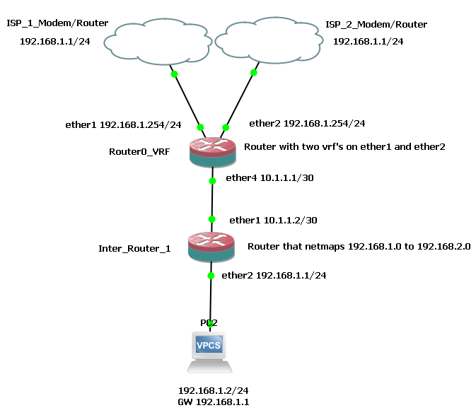
Ok, so here is a possible solution making use of two routers, working, at least in GNS3.
There isn’t yet any “advanced” failover function implemented.
And the base question still remains, is it possible to do the same with only one router (using somehow internally the netmap function that is now in the second router or using some of the other Mikrotik magic tiricks)?
Configuration of Router0_VRF:
[admin@Router0_VRF] > /export
# 2023-11-24 16:43:46 by RouterOS 7.11.2
# software id =
#
/interface ethernet
set [ find default-name=ether1 ] disable-running-check=no
set [ find default-name=ether2 ] disable-running-check=no
set [ find default-name=ether3 ] disable-running-check=no
set [ find default-name=ether4 ] disable-running-check=no
set [ find default-name=ether5 ] disable-running-check=no
set [ find default-name=ether6 ] disable-running-check=no
set [ find default-name=ether7 ] disable-running-check=no
set [ find default-name=ether8 ] disable-running-check=no
/disk
set slot1 slot=slot1 type=hardware
set slot2 slot=slot2 type=hardware
set slot3 slot=slot3 type=hardware
/interface list
add comment=defconf name=WAN
add comment=defconf name=LAN
/interface wireless security-profiles
set [ find default=yes ] supplicant-identity=MikroTik
/ip vrf
add interfaces=ether1 name=vrf1
add interfaces=ether2 name=vrf2
/port
set 0 name=serial0
/interface list member
add interface=ether1 list=WAN
add interface=ether2 list=WAN
add interface=ether3 list=WAN
add interface=ether4 list=LAN
add interface=ether5 list=LAN
/ip address
add address=192.168.1.254/24 interface=ether1 network=192.168.1.0
add address=192.168.1.254/24 interface=ether2 network=192.168.1.0
add address=10.1.1.1/30 interface=ether4 network=10.1.1.0
/ip firewall nat
add action=src-nat chain=srcnat src-address=192.168.2.0/24 to-addresses=\
    192.168.1.254
/ip route
add distance=1 dst-address=0.0.0.0/0 gateway=192.168.1.1@vrf1 routing-table=\
    main
add distance=2 dst-address=0.0.0.0/0 gateway=192.168.1.1@vrf2 routing-table=\
    main
add dst-address=192.168.2.0/24 gateway=10.1.1.2 routing-table=vrf1
add dst-address=192.168.2.0/24 gateway=10.1.1.2 routing-table=vrf2
/system identity
set name=Router0_VRF
/system note
set show-at-login=no
Configuration of Inter_Router_1:
[admin@Inter_Router_1] > /export
# 2023-11-24 16:30:28 by RouterOS 7.11.2
# software id =
#
/interface bridge
add name=bridge1
/interface ethernet
set [ find default-name=ether1 ] disable-running-check=no
set [ find default-name=ether2 ] disable-running-check=no
set [ find default-name=ether3 ] disable-running-check=no
set [ find default-name=ether4 ] disable-running-check=no
set [ find default-name=ether5 ] disable-running-check=no
set [ find default-name=ether6 ] disable-running-check=no
set [ find default-name=ether7 ] disable-running-check=no
set [ find default-name=ether8 ] disable-running-check=no
/disk
set slot1 slot=slot1 type=hardware
set slot2 slot=slot2 type=hardware
set slot3 slot=slot3 type=hardware
/interface wireless security-profiles
set [ find default=yes ] supplicant-identity=MikroTik
/port
set 0 name=serial0
/ip address
add address=10.1.1.2/30 interface=ether1 network=10.1.1.0
add address=192.168.1.1/24 interface=ether2 network=192.168.1.0
/ip firewall nat
add action=netmap chain=srcnat src-address=192.168.1.0/24 to-addresses=\
    192.168.2.0/24
add action=netmap chain=dstnat dst-address=192.168.2.0/24 to-addresses=\
    192.168.1.0/24
/ip route
add gateway=10.1.1.1
/system identity
set name=Inter_Router_1
/system note
set show-at-login=no
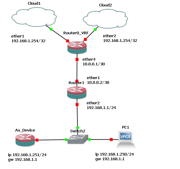
So, a simpler setup with two routers seems to be (no netmap in the intermediate router):
Router0_VRF:
#reproducible from blank CHR

/ip vrf
add interfaces=ether2 name=vrf2
add interfaces=ether1 name=vrf1

/ip address
add address=192.168.1.254 interface=ether1 network=192.168.1.1
add address=192.168.1.254 interface=ether2 network=192.168.1.1
add address=10.0.0.1/30 interface=ether4 network=10.0.0.0


/ip firewall nat
add action=src-nat chain=srcnat out-interface=ether1 to-addresses=\
    192.168.1.254
add action=src-nat chain=srcnat out-interface=ether2 to-addresses=\
    192.168.1.254

/ip route
add distance=1 dst-address=0.0.0.0/0 gateway=192.168.1.1@vrf1 routing-table=\
    main
add distance=2 dst-address=0.0.0.0/0 gateway=192.168.1.1@vrf2 routing-table=\
    main
add dst-address=192.168.1.0/24 gateway=10.0.0.2 routing-table=\
    vrf2
add dst-address=10.0.0.0/30 gateway=10.0.0.2 routing-table=vrf1
add dst-address=10.0.0.0/30 gateway=10.0.0.2 routing-table=vrf2
add dst-address=192.168.1.0/24 gateway=10.0.0.2 routing-table=\
    vrf1
add dst-address=192.168.1.0/24 gateway=10.0.0.2 routing-table=main

/system identity
set name=Router0_VRF
Router 1:
#reproducible from blank CHR


/ip address
add address=10.0.0.2/30 interface=ether1 network=10.0.0.0
add address=192.168.1.1/24 interface=ether2 network=192.168.1.0


/ip route
add gateway=10.0.0.1

/system identity
set name=Router1
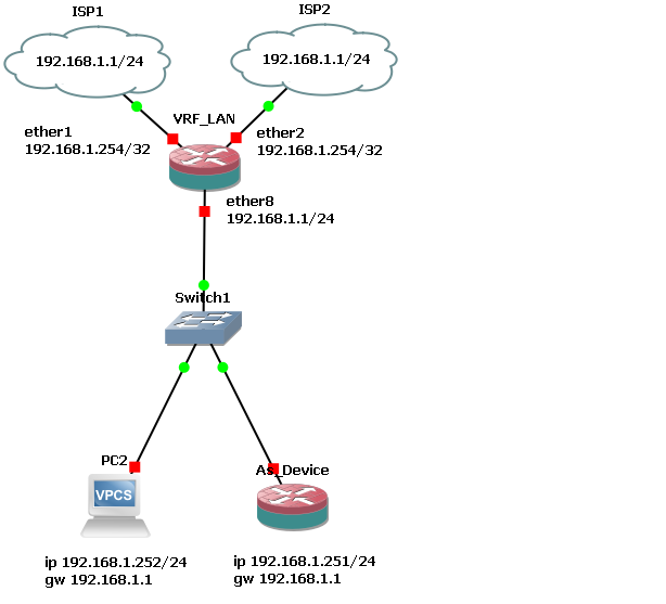
And - finally - this should be a possible solution with only one router. 
VRF_LAN:
#reproducible from blank CHR

/ip vrf
add interfaces=ether2 name=vrf2
add interfaces=ether1 name=vrf1

/ip address
add address=192.168.1.254 interface=ether1 network=192.168.1.1
add address=192.168.1.254 interface=ether2 network=192.168.1.1
add address=192.168.1.1/24 interface=ether8 network=192.168.1.0

/ip firewall nat
add action=src-nat chain=srcnat out-interface=ether1 to-addresses=\
    192.168.1.254
add action=src-nat chain=srcnat out-interface=ether2 to-addresses=\
    192.168.1.254

/ip route
add distance=1 dst-address=0.0.0.0/0 gateway=192.168.1.1@vrf1 routing-table=\
    main
add distance=2 dst-address=0.0.0.0/0 gateway=192.168.1.1@vrf2 routing-table=\
    main
add dst-address=192.168.1.0/24 gateway=ether8 routing-table=vrf1
add dst-address=192.168.1.0/24 gateway=ether8 routing-table=vrf2

/system identity
set name=VRF_LAN
It is fairly simple (I made a few other tests with different setups but they were all more complex, using a third VRF to emulate the previous two-routers solution or using some scripts to enable/disable interfaces and routes).
Still I don’t know exactly how/why it works (and maybe it doesn’t actually work on real hardware, only in GNS3), very likely it is some magic related to the /32 connection to the ISP router(s) AND to the “isolation” (or whatever) of the VRF’s that combined together allow the “back” route to ether8 and to the LAN.
 no magic here, it works exactly as intended …
Maybe if you can be a bit more specific on what part is still not clear in you mind I can try to explain.
Well, a good half (not really, I am joking) of posts on the board revolve around routers being designed to route and thus needing different networks or subnets on the LAN and WAN sides of the router.
Though (for whatever reasons) I have been exempted by the most harsh “you should change the addresses on your LAN (or WAN) side” suggestions, i have seen so many of them directed to other beginner users that I doubted it was possible at all, as I posted earlier, the only (partial) reference to a router that is “transparent” (in the sense that can be manually by-passed in case of failure) was about a particular setup involving a Draytek router on an Italian forum.
In my (perverted) mind the usefulness of this kind of setup (introducing a failover solution that is removable in case of need by simply moving a few cables) is so obvious that I believed it was a common and established approach.
The “final” solution (provided it works in the real word, outside GNS3) is actually pretty much simple while I expected it to be incredibly complex, given the number of posts suggesting to redesign the network as first step.
Surely the whole VRF stuff is mis-documented (if documented at all) and besides vague references to it here and there there are no (or I was unable to find them) clear explanations on how/why they work.
This particular kind of VRF (that you proposed) has essentially a “in-interface” outside the VRF and the “out-interface” inside it[1], but during my semi-random experiments (replacing the intermediate router in the two router solution with a third VRF on main router) I managed also to create a VRF with both in and out interfaces inside it (though it produced some quirks in tracing to 8.8.8.8 ). It is another thing I still need to experiment with,
I also tested an even crazier setup, using the CHR as a switch with two connections to each ISP modem/router (two cables/interfaces used for each modem), one to monitor the connection and one to be enabled/disabled in case of need.
This latter worked but - not unlike the actual physical test I made with the old, cheap TP-Link routers) - suffered from some stickiness (probably due to arp cache) when interfaces were enabled/disabled. Very likely it represents an alternative solution if I can manage somehow to manage duplicate MAC addresses (or whatever), but this is an exercise in futility that I will keep for later.
[1] which is I believe what makes the need of default gateway (0.0.0.0/0) to be put in “main” table BUT pointing to an IP on @vrf1 or @vrf2 AND the “return” route to be inside the vrf1 or vrf2 routing-tables BUT pointing to ether8 in “main”. What I suspect (though I’ll have to make a couple experiments) is that one of the keys to have the setup working is the use of a /32 address to connect to the ISP modem(s)/router(s) that allows the “return” route.
I think the key lesson here is what you said: not that many people know about VRFs and how to use it, hence the many responses asking you to change the IP addresses.
VRFs allow precisely what you are looking for: using the same IP ranges on different interfaces and be able to route the traffic. This page here explains it well: https://avinetworks.com/glossary/virtual-routing-and-forwarding-vrf/
Note that strictly speaking nothing forbids from using the IPs on different interfaces even without VRFs for as long as they are not in the same broadcast domain (otherwise you would have a problem of conflicting IPs). But the problem is: how to route packets between the interfaces if they share the same subnets? And that’s were the VRFs are helping. There are other possibilities as I demonstrated with my solution based on proxy-arp.
The /32 address creates a point-to-point link, I don’t think you need it in this scenario, but why not.
I think that the real issue is that (this is not only on this forum, it is common enough) there is a lack of understandable (for the newbies[1]) explanations about the way things work (or fail to work), and - even when they exist - they are in crumbles here and there on several unconnected threads, so that putting them together is extremely difficult.
The official help/wiki is among the worst documentation I have ever seen[2] , the forum is essentially on the shoulder of a handful of (knowledgeable/expert) volunteers that - while providing lots of good information - tend to be either very cryptic in their explanations (if any) or manage to spread the info all over the board, with topics that slowly (but surely) go astray.
Only as an example, I was looking for a failover method (it seems like as said before there are 2, 3 or more different possible methods to do anything in Mikrotik) and found the (supposedly complete/reproducible/tutoring) one by Chupaka here:
http://forum.mikrotik.com/t/advanced-routing-failover-without-scripting/136599/1
that starts with a configuration needing either mangle or routing rules to assign routing marks (while completely failing to provide the actual rules) then - slowly - (but seemingly without an actual explanation) it turns into a completely different method with no routing marks (thus easier) but that is not explained, and this is brought forward through (seemingly partial) snippets of configuration, then at a certain point there is this:
http://forum.mikrotik.com/t/advanced-routing-failover-without-scripting/136599/1
which brings us to this example by rextended:
http://forum.mikrotik.com/t/wan-load-balancing-between-2-isps-one-with-cgnat-and-another-in-bridge-mode-real-ipv4-address/150195/8
(which BTW is on a thread titled "WAN Load Balancing between 2 ISPs - one with CGNAT and another in bridge mode (real IPV4 address) ", in practice no way to find it with common searching)
that looks nice and simple but that I cannot understand at all how it works (if it works).
On the thread there are a couple similar ones by anav (as well without a real explanation and some are also in a dubitative form.
So I will have to reproduce those setups in GNS3, test if the whole stuff is actually working, see if I can understand how it works, then try to adapt it to the VRF solution.
The method Filo posted a link to earlier on this thread:
http://forum.mikrotik.com/t/simpler-failover-for-two-gateways-i-found-working/169108/1
is seemingly simpler AND it is explained (but on the other hand needs to be translated back to actual commands) though I am struggling to understand how it can be extended from dual to triple failover.
Doing “random” tests in order to be able to use the latter (Filo’s) method in a triple failover, I tried using (again) two routers in cascade, each doing dual failover (router0 with ISP1 connected to ether1/vrf1 and ISP2 connected to ether2/vrf2 and BEFORE it a router1 with router0 connected to ether1/vrf1 and “last resort” ISP3/LTE connected to ether2/vrf2).
I was surprised (not really, Murphy’s Laws are a thing) that it didn’t work as expected, in the sense that what I thought was a “transparent” router seems to be not-so-transparent and I had to use a different subnet between the routers to have the setup (almost) working.
As soon as I wiil have time to do more tests I will post this (yet another) configuration in a reproducible form.
The whole stuff is a real PITA, but on the other hand it is actually fun  , so it is not wasted time, it is a (still in my perverted mind) a form of entertainment.
[1] but then if everyone was an expert in the matter and knew everything the forum would probably have no reason to exist
[2] typically a page on the wiki lists 25 possible commands/options, half of which self-referencing, then provides 1 or 2 (incomplete) examples making use of just one or two of the 25 listed commands/options
Now that you have the VRFs configured the simple failover is quite easy to implement, I’ll explain what I did and you can customize to your own needs.
I have two routes to 0.0.0.0/0 in the main routing table leading to each one of my ISPs, one with higher preference (i.e. lower distance) than the other:
/ip route
add distance=2 dst-address=0.0.0.0/0 gateway=192.168.1.1@vrf-starlink routing-table=main comment="RouteStarlink"
add distance=3 dst-address=0.0.0.0/0 gateway=192.168.1.1@vrf-orange routing-table=main comment="RouteOrange"
So with this in a normal situation the route with the lowest distance, through the vrf-starlink, will be preferred. The trick consists in changing the distance of the other route to 1 when Starlink is down so that it becomes the preferred route due to the lower distance (because 1 < 2).
To detect if Starlink is down I have a /32 route to a gateway inside the Starlink infra, which I force through the Starlink VRF, which I will be checking with NetWatch. If the ping fails (timeout), the priority of my secondary route will be brought from 3 down to 1 so that it becomes the preferred route.
/ip route
add dst-address=100.64.0.1/32 routing-table=main gateway=192.168.1.1@vrf-starlink
/tool/netwatch
add host=100.64.0.1 interval=10 timeout=5 up-script=":log error \"starlink is up\";/ip route set distance=3 [find comment=\"RouteOrange\"];:log error \"route orange deprioritized\";" down-script=":log error \"starlink down\";/ip route set distance=1 [find comment=\"RouteOrange\"];:log error \"route orange prioritized\""
So the distance of my least preferred route will change from 3 to 1 depending on the availability of my most preferred ISP, which will keep its distance of 2.
You can follow the same logic to switch between 3 ISPs if you are able to rank them “most preferred”, “second preferred” and “least preferred”. The most preferred could for example have a distance of 1 in normal condition, and 4 if down, the second most preferred could have 2 if up and 5 if down, and the third preferred could have a distance of 3.
Of course we are not talking about load balancing here, just fail-over.
Also the fail-over process is slow, typically from a client perspective it takes between 15 seconds and 1 minute depending on the application.
Thanks.
Your approach seems simple enough (similar to the one by Filo) making use of distance, but there is no need of an added routing table nor of mangle mark routing, I like it.
With three connections should be (very loosely) something like this:
/ip route
#following route is the main one and stays fixed to distance 20
add distance=20 dst-address=0.0.0.0/0 gateway=192.168.1.1@vrf1 routing-table=main comment="ISP_1"
#following route is second best and flips between 10 (when used) and 30 (in normal operation)
add distance=30 dst-address=0.0.0.0/0 gateway=192.168.1.1@vrf2 routing-table=main comment="ISP_2"
#following route is the least desirable (LTE in my case) and flips between 15 (when used) and 40 (in normal operation)
add distance=40 dst-address=0.0.0.0/0 gateway=192.168.1.1@vrf3 routing-table=main comment="ISP_3"
#following route is to test connectivity of ISP_1 using 1.1.1.1 as gateway
add dst-address=1.1.1.1/32 routing-table=main gateway=192.168.1.1@vrf1
#following route is to test connectivity of ISP_2 using 4.4.2.1 as gateway
add dst-address=4.4.2.1/32 routing-table=main gateway=192.168.1.1@vrf2
#following route is to test connectivity of ISP_3 using 4.4.2.2 as gateway
add dst-address=4.4.2.2/32 routing-table=main gateway=192.168.1.1@vrf3
Now, when it comes to the netwatch scripts things become a little murkier.
I am posting what I think might work but I won’t be able to test and report/correct for a couple of days.
(only trying to separate the up and down scripts from netwatch entry as it seems “cleaner” and easier to read
/tool/netwatch
add host=1.1.1.1 interval=10 timeout=5 up-script=Use_ISP_1 down-script=Use_ISP_2
add host=4.4.2.1 interval=10 timeout=5 up-script=Use_ISP_2 down-script=Use_ISP_3
add host=4.4.2.2 interval=10 timeout=5 up-script=Use_ISP_3 down-script=Total_Fail
and scripts should be something like (without comments/log info etc. to make them more readable):
/system script
# this demotes ISP_2 and ISP_3 to their normal 30 and 40 distance
 add name=Use_ISP_1 source={/ip route set distance=30 [ find comment=\"ISP_2\" ]; /ip route set distance=40 [ find comment=\"ISP_3\" ])
 #this promotes ISP_2 to distance 10 and demotes ISP_3 to its normal 40 (if needed)
 add name=Use_ISP_2 source={/ip route set distance=10 [ find comment=\"ISP_2\" ]; /ip route set distance=40 [ find comment=\"ISP_3\" ])
 #this promotes ISP_3 to distance 15 and demotes ISP_2 to its normal 30 distance
 add name=Use_ISP_3 source={/ip route set distance=15 [ find comment=\"ISP_3\" ] ; /ip route set distance=30 [ find comment=\"ISP_2\" ] )
 add name=Total_Fail source={<I will put here such things ... what they are, yet  I know not, but they shall be the terrors of the network> )
The above cannot relly work “as is”, a check of some kind needs to be added, otherwise when in “normal” operation (with ISP_1 up) a failure of ISP_2 will trigger the Use_ISP_3 and either Use_ISP_1 will conflict (attempting to flip ISP_3 back to distance 40, that then will be re-upped to 15 by Use_ISP2) or it will do nothing and the connection will remain on the ISP_3 until something else happens.
If I get right the documentation the up-script is only executed when connection status changes from down to up and the down-script only when the connection status changes from up to down.
So if the connection on ISP_1 remains up, the up-script Use_ISP_1 is never executed.
It shouldn’t be a problem, just a matter of learning a bit more of Mikrotik script language in order to make the promotions/demotions conditional on the current distance situation of other interfaces.
Ok, so I didn’t manage (yet) to find the time to study the scripting language and learn enough to be confident in writing the triple WAN failover script, but I managed to find what was the issue with my concept of “transparent” router (with two vrf’s).
A (stupid) error using more than one router with same “outbound” addresses . 
With non-duplicate addresses the concept works.
As (possibly an exercise in futility) I made a POC in GNS3/CHR which seems completely crazy until you realize that all the VRF_xxx routers have the same configuration (bar the “outbound” interfaces addresses) and are as a matter of fact interchangeable so that you can have a spare one or two with exactly the same configuration (but with a different IP on the “outbound” interfaces) that can be replaced by anyone by simply disconnecting and re-connecting the cables.
The configuration uses a netwatch 2 WAN failover approach derived from mtest001’s nice one.
Of course the second VRF and the netwatch scripts in VRF_252, VRF_251 and VRF_250 are unneeded.
Here is the reproducible configuration for VRF_253:
#reproducible from blank CHR
# this is for VRF_253 with "outbound" interfaces set to 192.168.1.253
# in Notepad you can use Find and replace with 253 and the IP you want 254, 252, etc.
#
# the 253 is in 5 places:
# 2 times in /ip address, for ether1 and ether2
# 2 times in /ip firewall nat, for ether1 and ether2
# in /system identity name

/ip vrf
add interfaces=ether1 name=vrf1
add interfaces=ether2 name=vrf2

/ip address
add address=192.168.1.1/24 interface=ether8 network=192.168.1.0
add address=192.168.1.253 interface=ether1 network=192.168.1.1
add address=192.168.1.253 interface=ether2 network=192.168.1.1

/ip firewall nat
add action=src-nat chain=srcnat out-interface=ether1 to-addresses=\
    192.168.1.253
add action=src-nat chain=srcnat out-interface=ether2 to-addresses=\
    192.168.1.253

/ip route
add comment=Primary_ISP distance=2 dst-address=0.0.0.0/0 gateway=\
    192.168.1.1@vrf1 routing-table=main
add comment=Next_ISP distance=3 dst-address=0.0.0.0/0 gateway=\
    192.168.1.1@vrf2 routing-table=main
add dst-address=192.168.1.0/24 gateway=ether8 routing-table=vrf1
add dst-address=192.168.1.0/24 gateway=ether8 routing-table=vrf2
add dst-address=1.1.1.1/32 gateway=192.168.1.1@vrf1 routing-table=main

/system identity
set name=VRF_253

/system script
add dont-require-permissions=yes name=Use_Primary owner=admin policy=\
    read,write,test source=":log error \"Use_Primary says Primary_ISP is up\";\
    /ip route set distance=3 [ find comment=\"Next_ISP\" ]"
add dont-require-permissions=yes name=Use_Next owner=admin policy=\
    read,write,test source=":log error \"Use_next says Primary_ISP is down\";/\
    ip route set distance=1 [ find comment=\"Next_ISP\" ]"
/tool netwatch
add down-script=Use_Next host=1.1.1.1 interval=10s timeout=5s type=simple \
    up-script=Use_Primary
Tracing from the “As_device” router has three or four hops of 192.168.1.1:
[admin@MikroTik] /ip/address> /tool trace 8.8.8.8
Columns: ADDRESS, LOSS, SENT, LAST, AVG, BEST, WORST, STD-DEV
 #  ADDRESS          LOSS  SENT  LAST    AVG   BEST  WORST  STD-DEV
 1  192.168.1.1      0%       4  1.8ms   2.5   1.8   4.3    1.1
 2  192.168.1.1      0%       4  2.3ms   2.3   2     2.5    0.2
 3  192.168.1.1      0%       4  4.7ms   5     4.5   5.8    0.5
 4  88.48.86.232     0%       4  11.5ms  11    10.1  11.8   0.7
 5  172.17.107.136   0%       4  11.9ms  10.7  10    11.9   0.7
 6  172.19.184.70    0%       4  14.7ms  14    13.2  14.7   0.6
 7  172.19.177.62    0%       4  15.3ms  14.7  14.5  15.3   0.3
 8  195.22.205.116   0%       4  15ms    14.5  13.6  15     0.6
 9  142.250.168.148  0%       4  14.9ms  14.5  14    14.9   0.3
10  72.14.239.144    0%       4  15.3ms  22.5  15.3  42.4   11.5
11  142.251.235.179  0%       4  14.9ms  23.1  14.9  46.9   13.7
12  8.8.8.8          0%       4  14.6ms  21.8  14.6  43.2   12.4
and, with first ISP disabled:
[admin@MikroTik] /ip/address> /tool trace 8.8.8.8
Columns: ADDRESS, LOSS, SENT, LAST, AVG, BEST, WORST, STD-DEV
 #  ADDRESS          LOSS  SENT  LAST    AVG   BEST  WORST  STD-DEV
 1  192.168.1.1      0%       8  1.6ms   2     1.4   3.1    0.5
 2  192.168.1.1      0%       8  2.2ms   2.4   1.8   3.6    0.5
 3  192.168.1.1      0%       8  3.1ms   7.5   2.7   39     11.9
 4  192.168.1.1      0%       8  5.4ms   10.8  4.5   49.9   14.8
 5  88.48.86.232     0%       8  11.9ms  11.6  10.4  14.9   1.4
 6  172.17.107.136   0%       8  11.8ms  11.5  10.8  12.4   0.5
 7  172.19.184.70    0%       8  14.4ms  14.9  14.3  15.4   0.4
 8  172.19.177.62    0%       8  15.7ms  15.5  15    16.1   0.4
 9  195.22.205.116   0%       8  15.3ms  15.4  14.5  16.6   0.7
10  142.250.168.148  0%       8  15.9ms  15.3  14.4  16     0.5
11  72.14.239.144    0%       8  15.8ms  25.4  15.6  55.7   16.1
12  142.251.235.179  0%       8  15.8ms  22.1  15.3  40.5   10.5
13  8.8.8.8          0%       8  15.6ms  22.2  15.1  43.9   11.6
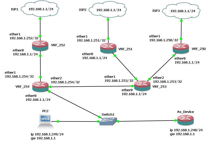
Ok, so this is the reproducible version with 3 WAN failover via VRF.
/ip vrf
add interfaces=ether3 name=vrf3
add interfaces=ether1 name=vrf1
add interfaces=ether2 name=vrf2

/ip address
add address=192.168.1.254 interface=ether1 network=192.168.1.1
add address=192.168.1.254 interface=ether2 network=192.168.1.1
add address=192.168.1.254 interface=ether3 network=192.168.1.1
add address=192.168.1.1/24 interface=ether8 network=192.168.1.0


/ip firewall nat
add action=src-nat chain=srcnat out-interface=ether1 to-addresses=\
    192.168.1.254
add action=src-nat chain=srcnat out-interface=ether2 to-addresses=\
    192.168.1.254
add action=src-nat chain=srcnat out-interface=ether3 to-addresses=\
    192.168.1.254

/ip route
add comment=Primary_ISP distance=3 dst-address=0.0.0.0/0 gateway=\
    192.168.1.1@vrf1 routing-table=main
add comment=Next_ISP disabled=no distance=4 dst-address=0.0.0.0/0 gateway=\
    192.168.1.1@vrf2 routing-table=main
add dst-address=192.168.1.0/24 gateway=ether8 routing-table=vrf1
add dst-address=192.168.1.0/24 gateway=ether8 routing-table=vrf2
add dst-address=1.1.1.1/32 gateway=192.168.1.1@vrf1 routing-table=vrf1
add comment=LTE_Last disabled=no distance=5 dst-address=0.0.0.0/0 gateway=\
    192.168.1.1@vrf3 routing-table=main
add dst-address=192.168.1.0/24 gateway=ether8 routing-table=vrf3
add dst-address=4.2.2.1/32 gateway=192.168.1.1@vrf2 routing-table=vrf2
add dst-address=4.2.2.2/32 gateway=192.168.1.1@vrf3 routing-table=vrf3

/system identity
set name=VRF_254


/system script
add dont-require-permissions=yes name=Primary_running owner=admin policy=\
    read,write,test source=":log error \"Primary_running says Primary_ISP is u\
    p\";/ip route set distance=4 [ find comment=\"Next_ISP\" ];/ip route set d\
    istance=5 [ find comment=\"LTE_Last\" ];/tool netwatch disable [ find comm\
    ent=\"Next\" ];/tool netwatch disable [ find comment=\"LTE\" ]"
add dont-require-permissions=yes name=Use_Next owner=admin policy=\
    read,write,test source=":log error \"Use_next says Primary_ISP is down\";/\
    ip route set distance=1 [ find comment=\"Next_ISP\" ];/ip route set distan\
    ce=5 [ find comment=\"LTE_Last\" ];/tool netwatch enable [ find comment=\"\
    Next\" ];/tool netwatch disable [ find comment=\"LTE\" ]"
add dont-require-permissions=yes name=Next_running owner=admin policy=\
    read,write,test source=":log error \"Next_running says Next_ISP is up\";/i\
    p route set distance=1 [ find comment=\"Next_ISP\" ];/ip route set distanc\
    e=5 [ find comment=\"LTE_Last\" ];/tool netwatch disable [ find comment=\"\
    LTE\" ]"
add dont-require-permissions=yes name=Use_LTE_Last owner=admin policy=\
    read,write,test source=":log error \"Use_LTE_Last says Next_ISP is down\";\
    /ip route set distance=4 [ find comment=\"Next_ISP\" ];/ip route set dista\
    nce=2 [ find comment=\"LTE_Last\" ];/tool netwatch enable [ find comment=\
    \"LTE\" ]"
add dont-require-permissions=yes name=LTE_running owner=admin policy=\
    read,write,test source=":log error \"LTE_running says LTE_Last is up\""
add dont-require-permissions=yes name=LTE_fail owner=admin policy=\
    read,write,test source=":log error \"LTE_fail says LTE_Last is down\""

/tool netwatch
add comment=Primary disabled=no down-script=Use_Next host=1.1.1.1@vrf1 \
    interval=10s timeout=5s type=simple up-script=Primary_running
add comment=Next disabled=yes down-script=Use_LTE_Last host=4.2.2.1@vrf2 \
    interval=10s timeout=5s type=simple up-script=Next_running
add comment=LTE disabled=yes down-script=LTE_fail host=4.2.2.2@vrf3 interval=\
    10s timeout=5s type=simple up-script=LTE_running
The netwatch scripts I used are extremely simple and (IMHO) far from smart or elegant in any way, yet they seem to work just fine.
As soon as I started congratulating with myself for having managed to half-@§§edly put together something working, the new Ax Lite’s I ordered came in and (even if it took more time than expected) I succeeded to replicate, adapting it to the 4 ports, the settings, and the next problem came out:
it seems that there is no way to make the Mikrotik device to perform DNS resolution through a vrf (if there is a way I couldn’t find how to have it working in this setup), which means that you don’t have NTP as well (it seems like you cannot even try using directly an IP address for a NTP server, you need to use its name and let the router resolve it through DNS).
For the same reason also online update to 7.12.1 (from the factory installed 7.8 version ) wasn’t possible.
I had to make a couple routes in main (disabling/removing one of the VRF’s) to be able to have DNS (and consequently NTP and software update) working.
BTW and only as a side note, I found out that (for whatever reason) the “resolve” command - while throwing an error if no DNS is found - outputs nothing if used normally on command line, and needs to be invoked like:
put [:resolve google.com]
or :
put [:resolve domain-name=google.com server=8.8.8.8]
Nothing to make a fuss about, but using “resolve google.com” or “resolve domain-name=google.com”, etc. should throw an error or a warning and not a “newline”.
In this specific case, one could be happy with the router set to any random date/time (even if going back to the '70’s seems a bit of a stretch) and as well the resolving through DNS may be unneeded, still it looks “wrong”.
I am not finished with this.
I am experimenting with removing the VRF1 (moving the Primary ISP connection to “main”) and creating a new VRF on the LAN side.
So far it seems to be working , but I have to do more tests to be sure.
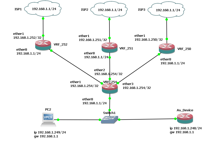
And this is the 3 WAN failover with “reversed” VRF and no netwatch/no scripting (using recursive).
The reproducible in CHR:
/ip vrf
add interfaces=ether8 name=vrf8

/ip address
add address=192.168.1.241 interface=ether1 network=192.168.1.1
add address=192.168.1.242 interface=ether2 network=192.168.1.1
add address=192.168.1.243 interface=ether3 network=192.168.1.1
add address=192.168.1.1/24 interface=ether8 network=192.168.1.0


/ip firewall nat
add action=src-nat chain=srcnat out-interface=ether1 to-addresses=\
    192.168.1.241
add action=src-nat chain=srcnat out-interface=ether2 to-addresses=\
    192.168.1.242
add action=src-nat chain=srcnat out-interface=ether3 to-addresses=\
    192.168.1.243

/ip route
add dst-address=192.168.1.0/24 gateway=ether8@vrf8
add check-gateway=ping comment=main_ISP1_Route disabled=no distance=1 \
    dst-address=0.0.0.0/0 gateway=1.1.1.1@vrf8 routing-table=main scope=30 \
    target-scope=11
add check-gateway=ping comment=main_ISP2_Route disabled=no distance=2 \
    dst-address=0.0.0.0/0 gateway=4.2.2.1@vrf8 routing-table=main scope=30 \
    target-scope=11
add check-gateway=ping comment=main_ISP3_Route disabled=no distance=3 \
    dst-address=0.0.0.0/0 gateway=4.2.2.2@vrf8 routing-table=main scope=30 \
    target-scope=11
add comment=vrf8_ISP1_Ping disabled=no distance=1 dst-address=1.1.1.1 \
    gateway=192.168.1.1%ether1 routing-table=vrf8 scope=10 target-scope=10
add comment=vrf8_ISP2_Ping distance=2 dst-address=4.2.2.1 gateway=\
    192.168.1.1%ether2 routing-table=vrf8 scope=10 target-scope=10
add comment=vrf8_ISP3_Ping distance=3 dst-address=4.2.2.2 gateway=\
    192.168.1.1%ether3 routing-table=vrf8 scope=10 target-scope=10
add check-gateway=ping comment=vrf8_ISP1_Route disabled=no distance=1 \
    dst-address=0.0.0.0/0 gateway=1.1.1.1@vrf8 routing-table=vrf8 scope=30 \
    target-scope=11
add check-gateway=ping comment=vrf8_ISP2_Route disabled=no distance=2 \
    dst-address=0.0.0.0/0 gateway=4.2.2.1@vrf8 routing-table=vrf8 scope=30 \
    target-scope=11
add check-gateway=ping comment=vrf8_ISP3_Route disabled=no distance=3 \
    dst-address=0.0.0.0/0 gateway=4.2.2.2@vrf8 routing-table=vrf8 scope=30 \
    target-scope=11
/system identity
set name=VRF_253_2nd
The routing looks a little bit crazy (IMHO) but it seems to be working:
[admin@VRF_253_2nd] /ip/route> print
Flags: D - DYNAMIC; A - ACTIVE; c - CONNECT, s - STATIC; + - ECMP
Columns: DST-ADDRESS, GATEWAY, DISTANCE
#      DST-ADDRESS     GATEWAY             DISTANCE
;;; main_ISP2_Route
0   s  0.0.0.0/0       4.2.2.1@vrf8               2
;;; main_ISP1_Route
1  As  0.0.0.0/0       1.1.1.1@vrf8               1
;;; main_ISP3_Route
2   s  0.0.0.0/0       4.2.2.2@vrf8               3
3  As  192.168.1.0/24  ether8@vrf8                1
  DAc+ 192.168.1.1/32  ether3                     0
  DAc+ 192.168.1.1/32  ether2                     0
  DAc+ 192.168.1.1/32  ether1                     0
;;; vrf8_ISP3_Route
4   s  0.0.0.0/0       4.2.2.2@vrf8               3
;;; vrf8_ISP2_Route
5   s  0.0.0.0/0       4.2.2.1@vrf8               2
;;; vrf8_ISP1_Route
6  As  0.0.0.0/0       1.1.1.1@vrf8               1
;;; vrf8_ISP1_Ping
7  As  1.1.1.1/32      192.168.1.1%ether1         1
;;; vrf8_ISP2_Ping
8  As  4.2.2.1/32      192.168.1.1%ether2         2
;;; vrf8_ISP3_Ping
9  As  4.2.2.2/32      192.168.1.1%ether3         3
  DAc  192.168.1.0/24  ether8@vrf8                0
Adding the google dns servers:
/ip dns
set allow-remote-requests=yes servers=8.8.8.8,8.8.4.4
DNS queries resolve fine:
[admin@VRF_253_2nd] > /put [:resolve google.com]
142.250.180.174
As well adding a NTP server:
/system ntp client
set enabled=yes
/system ntp client servers
add address=ntp1.inrim.it
NTP is fine:
[admin@VRF_253_2nd] /system/ntp/client> print
         enabled: yes
            mode: unicast
         servers: ntp1.inrim.it
             vrf: main
      freq-drift: 0 PPM
          status: synchronized
   synced-server: ntp1.inrim.it
  synced-stratum: 1
   system-offset: -2.956 ms
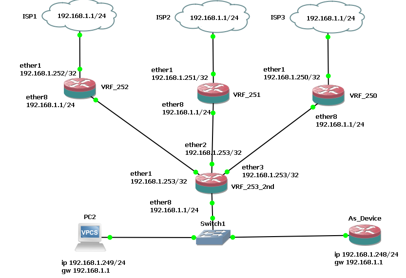
Ok, so it is more than two months that the setup described in post #37 is up and running.
It did work in all simulations/tests I made and it has worked just fine in one instance where the ISP1 was down for a few minutes, performing the failover to ISP2 nicely and then going back to ISP1 when service returned.
Today there was the need for some work to be done on the electrical line, there was a planned interruption of energy, 15-20 minutes planned, to change some cables/wires outside the building.
As a precaution we shut off all the PC’s, just in case, but I left the “router stuff” connected (no UPS, I know), so when the electric company switched off the line routers/modems/switches went off.
When the energy was restored, I checked the internet connection and although all the devices were powered on and running, there was no internet.
Since the ISP1 modem is very slow at booting (while the ISP2 modem is much faster) I thought that the issue was with failover, ISP2 modem had already all the right lights on while the ISP1 one was still detecting the DSL/handshaking/whatever pinging 8.8.8.8 from a PC gave “host unreachable” (whilst pinging the Mikrotik hap ax lite lan address was fine).
So I connected to the hap ax lite with Winbox, and it had rebooted just fine (with the expected “router rebooted without proper shutdown, probably power outage” in log).
I then tried from terminal to ping 8.8.8.8 and for 6 or 7, maybe 8 pings it gave to me “no route …”, then it suddenly started responding normally and (obviously) internet was restored to the whole network.
I made a few attempts at manually power down/reboot the device and - checking the routes - all of them ( that should have normally been “AS” or “S”) were “USHI” (as if there was no cable connected to the WAN interfaces).
So, in terminal, tried again one single ping at the time, while keeping an eye on Routes window open:
ping 8.8.8.8 count=1
and, lo and behold, at the 8th ping (after 7 “no route …” replies) ping succeeded as normally and the routes became AS or S.
No idea why exactly this happens, maybe it is “normal”, but it doesn’t sound so (at least to me).
For the moment I added a Netwatch script on 8.8.8.8 that only logs if ping is successful (“up” script) and logs if ping is unsuccesful AND pings 8.8.8.8 10 times (“down” script).
The 10 pings change the status of the routes, so at next run of netwatch it succeeds.
I could only make a couple tests (as people without internet were starting to get mad at me), but it seems to work, even if it seems - besides primitive - also somewhat “ugly”.
Simple question what if one was to use this in routes…
/ip route
add distance=2 dst-address=0.0.0.0/0 gateway=192.168.1.1%ether1 routing-table=main comment=“RouteStarlink”
add distance=3 dst-address=0.0.0.0/0 gateway=192.168.1.1%ether2 routing-table=main comment=“RouteOrange”
add distance=4 dst-address=0.0.0.0/0 gateway=192.168.1.1%ether3 routing-table=main comment=“RouteBlue”
From what my reliable yoda told me, since I cannot find sheite in MT docs… aka what the @symbor or %symbol do in IP routes …
That if there is a single LAN, the above method should work.
Using VRF, is adding Virtual Routers, not vlans, to the mix and this works if you have three separate LANs as the LAN and WAN have to be in the same VRF.
Looking at the examples, at MT, VRF is used for vpns and single uses, not for LAN distribution.
My gateways are different from what you suggest:
;;; vrf8_ISP1_Ping
7 As 1.1.1.1/32 192.168.1.1%ether1 1
;;; vrf8_ISP2_Ping
8 As 4.2.2.1/32 192.168.1.1%ether2 2
;;; vrf8_ISP3_Ping
9 As 4.2.2.2/32 192.168.1.1%ether3 3
because of recursive failover, but they point in the same direction.
And BTW the ether1-3 are, in this “reversed VRF” approach, outside the VRF.
I have a LAN and 3 WANs.
Anyway the issue must lie somewhere else, a Route “USHI” is the same as the one for ISP_3 (which I haven’t - yet -connected in the “real” installation), for this latter I have (normal since there is no cable in the socket for ether3) the led off, for ether1 and 2 (and of course 4) I have the leds lit up.
It is like the ether1 and 2 “go to sleep” and need be awaken by *something", very likely besides the ping enabling/disabling the interfaces (or maybe also disabling/enabling the routes) would do as well.