I was reading about the possiblity of do Wireless bonding of two wi-fi cards, in my Mikrotik router’s, and I have found this manual page: http://wiki.mikrotik.com/wiki/Manual:Bonding_Examples , but in this page they use and create EoIP interfaces and they do bonding of them, and I do not understand why.
Why they do not do like in this page http://wiki.mikrotik.com/wiki/Bonding and do the bonding of the two wi-fi cards like they bond the two NIC cards? the bonding of wlan1 and wlan2 without EoIP interfaces?
Can someone advise me and tell me why they do not do the bonding of ‘wlan’ like they do with ‘ether’: [admin@Router1] interface bonding> add slaves=ether1,ether2
Have anyone tried to do this: [admin@Router1] interface bonding> add slaves=wlan1, wlan2 , with success.
All comments and advises will be very appreciated.
Bonding could be used only on OSI layer 2 (Ethernet level) connections. Thus you need to create EoIP interfaces on each of the wireless links. http://wiki.mikrotik.com/wiki/Bonding_Examples
@cybercoder; thanks for the answer and for your interest in my topic, but the thing that I do not understand is really that statement. Why Bonding could be used only on OSI layer 2 (Ethernet level) connections? And wireless works also on OSI Layer 2. What I’m trying to find is why they said that. That statement have to be based in some fact. What is the point and the subject in wireless level that forces Mikrotik to use EoIP interfaces when bonding in wireless.
Maybe there are a simple point that I’m missing.
More advises, comments, please…
@InoX: First thanks for the feedback, can you explain me better how do you do that.
You also said like the tutorial but which one, becuase I have posted two.
Just a question about the bonding you did. You said you used 2 SXT to do it. To what did you connect the 2 SXT’s? Where they both looking at 1 uplink or did they look at each other? If they looked at 1 uplink, did you the use a RB with 5 ports behind them to do the bonding?
2xRB750GL or any mikrotik router with gigabit, 2xSXT+2xSXT and Balance-rr. Radios were all in bridge, no other configuration needed. Configurations are on the routers between the ports with radios.
The radios were shielded and placed in the focal point of satellite dish antennas, it might not work with cheap antennas otherwise.
This is the tutorial i’ve used:
Router A
Log into your Mikrotik router
Create a Bonding interface: Here you tell the router which interfaces should be included in the bond. We are going to use round-robin mode, make ether1 and ether2 the slaves and give the interface a name of “bonding1”. The different modes are explained in Mikrotik’s Wiki/Bonding.
/interface bonding add slaves=ether1,ether2 name=bonding1 mode=balance-rr
Assign an IP to the bonding interface. Never assign ip’s to the slave interfaces themselves.
/ip address add address 192.168.0.10/24 interface=bonding1
Add Link Monitoring so your router knows when a link is having a problem. We will use ARP for link monitoring and tell the router to watch the ARP on 192.168.0.20. An explaniation of the different types of link monitoring can be found at Mikrotik’s Wiki/Bonding.
/interface bonding set bonding1 link-monitoring=arp arp-ip-targets=192.168.0.20
Router B
Log into your Mikrotik router
Create a Bonding interface: Here you tell the router which interfaces should be included in the bond. We are going to use round-robin mode, make ether1 and ether2 the slaves and give the interface a name of “bonding1”. The different modes are explained in Mikrotik’s Wiki/Bonding.
/interface bonding add slaves=ether1,ether2 name=bonding1 mode=balance-rr
Assign an IP to the bonding interface. Never assign ip’s to the slave interfaces themselves.
/ip address add address 192.168.0.20/24 interface=bonding1
Add Link Monitoring so your router knows when a link is having a problem. We will use ARP for link monitoring and tell the router to watch the ARP on 192.168.0.10. An explaniation of the different types of link monitoring can be found at Mikrotik’s Wiki/Bonding.
/interface bonding set bonding1 link-monitoring=arp arp-ip-targets=192.168.0.10
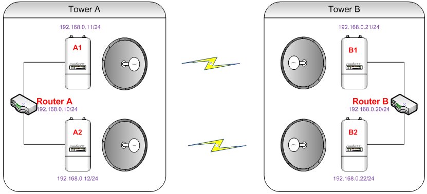
Ofcourse that radios needs to be connected between them, two wireless links like in the picture:
You dont have problem with latency and disorder packet?? Because I am using 2x rocket ac lite ans 2x rocket m5 and 2 x rb750g and I get only 25mbps using balance rr
There was no problem, the links worked for about 3 years until water found a way inside and reset one sxt to default. It was a well known design flaw. Both links must be set up very good because the weakest will dictate the speed.
LE
It wont work in the lab also. Just use cables between the ports and see if the traffic is distributed correctly.
It’s impossible to make 4 radios work in one room no matter the antennas.
I dont know what happens. I turn on radio in my offce and it works. I am using balance alb and its works but I noticed tht in certain time bonding was down and suddenly up. Is that normal? I used jperf to do one tcp connection and I get 90mbps and I using arp monitoring
If you are testing SXT’s in one room I would recommend reducing Tx Power on all radios so they perform better. Default Tx power in one room gives terrible results.
Make sure you choose different non-conflicting channels for each radio pair, use scan or frequency usage to choose the best two channels.
I also recommend to set devices to use manual-tx-power and all-rates-fixed=6
You should aim for Tx/Rx signal (in the registration table) of -40dB if possible. The closer it is to 0dB the worse the performance as the radios are “shouting” at each other.
It can also stop you getting a headache from all the RF
I have the same scheme with the difference that I made it with Mikrotik 2x750gr3 boards, wireless links with 2x RB911G-5HPacD +2xRB911G-5HPacD. I have the following problem. I can not ping from A to A1, A2, B1, B2. Or from B1 to A1, A2, B2. Ping from B to A1,A2,B1,B2 also not working. Pings between the two bonding A to B runs and works. I tried to put / 32 addresses on A1, A2, B1, B2 but still can not ping. In these boards I can only get in with mac-telnet. When the link works without bonding and puts addresses / 24 devices A1, A2 accesses them without any problems. Would you explain exactly how you do addressing and routing to have access to A1, A2, B1, B2. My topic is: http://forum.mikrotik.com/t/bonding-ping-problem/127348/1
Thanks in advance