cable-test on hap lite, pure madness

The other day cable-test features of Mikrotik/Ros happened to be mentioned here:
http://forum.mikrotik.com/t/hap-ax2-poe-port-suddenly-limited-to-100mbps/181713/1
and I remained with the curiosity about what each cable pair line/entry meant (the order they are shown could be either by wire colour/twisted pair or couple of pins on rj45, i.e. 1 and 2, 3 and 6, 4 and 5, 7 and 8 ), so I dig out of the box of things that may come useful one day an old (defective) self-crimped cable some 3 m long, then, with a probability of success of 50% I cut off one of the connectors.
Then tested the cable with a keystone socket and an already tested patch cable and I was lucky, the remaining connector and cable was good.

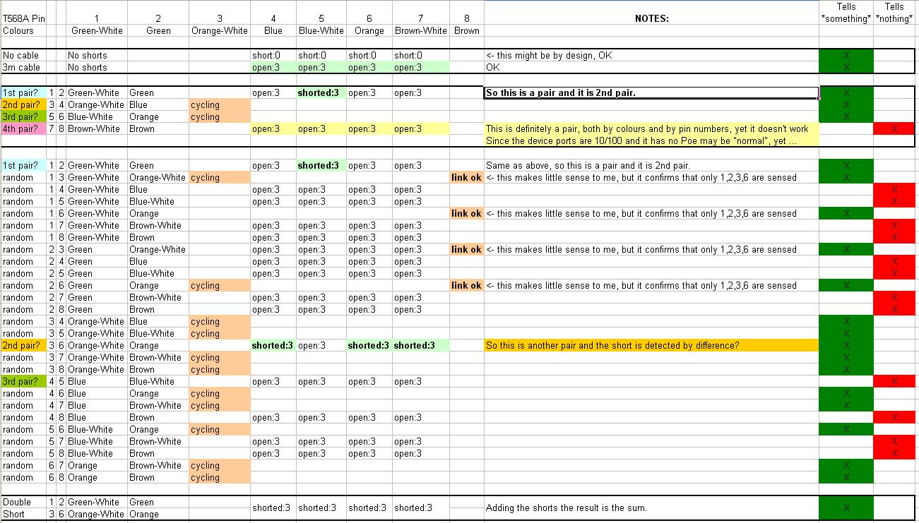
I had a hap lite handy (v6.49.17) and tested the cable-detect feature shorting the wires in every possible permutation (tried two ports, ether 3 and ether 4, to rule out the possibility that one port was defective).
The hap lite I have is the “tower” version (RB941-2nD-TC) but it should work the same as the “flat” version RB941-2nD (which is listed among the devices that sport the cable-detect feature) here:
https://help.mikrotik.com/docs/spaces/ROS/pages/8323191/Ethernet

Maybe the feature does not work properly specifically on the hap lite model I have, or maybe 6.49.17 is an unlucky release, but results were if not senseless, completely crazy.

The only pair short that is detected properly is 1-2 (Green and White/Green in T568A) and it is shown as shorted as second entry.
Short on pair 3-6 (Orange and White/Orange in T568A) can be detected indirectly as it creates a unique pattern (all entries BUT the second shown as shorted).

The rest was more or less “a suffusion of yellow”.

It could make sense that, since the device has no PoE and has 10/100 interfaces, only 1,2 and 3,6 pairs are analyzed/detected (even if “strangely”), but then the output should show that.

I did a couple more tests with good (but maybe too short) patch cables, simulating the shorts on a keystone socket, but the results were substantially the same as the ones in the image.

I will do some more tests with longer cables when I have some time, I should have a few 10 m ones somewhere …
cable_test.jpg

I did a bit of research, and as always (for some reasons every time I look at something in detail I find a can of worms) it is the actual standards (actually the lack of a single one) that are a mess.

So here is - for correctness and future memory - the situation:

Many European technical documents, old manufacturing sheets, and similar mistakenly state that DIN EN 50173 (or its international equivalent ISO/IEC 11801) numbers the twisted pairs based on mechanical pin positions.

This is false.

The DIN/ISO standard text focuses entirely on electrical performance, shielding, and connector geometries. It leaves "Pair Numbering" strictly to the raw cable manufacturing standards (like IEC 61156-5 / EN 50288), where pair numbers are bound entirely to wire colours, not connector slots (Pair 1 = Blue, Pair 2 = Orange, Pair 3 = Green, Pair 4 = Brown).

So we arrive to the Tester's Paradox: an Ethernet tester chip cannot physically look at the colour of the copper insulation inside the plug and it cannot apply a colour-based standard. It must evaluate copper lines mapping pairs to the physical pin contacts.

The other related standard is TIA 568, just like the DIN/ISO standard the mapping is between pairs and wire colours, NOT pin positions.

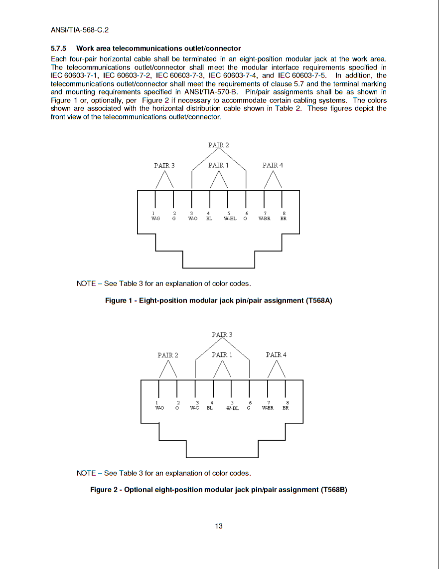
The TIA-568-C.2 August 2009 contains this:

From which it is clear that pair number depends on wire colours and not on pin positions.

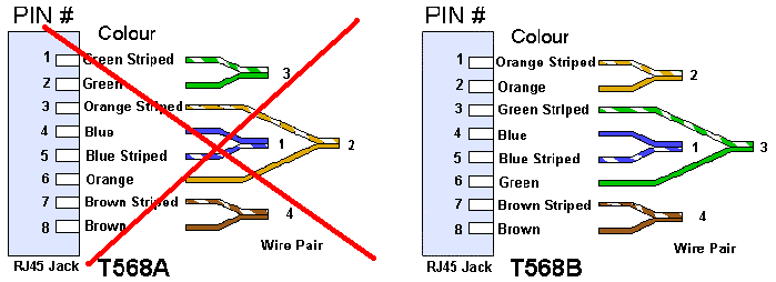
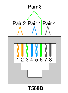
Given the prevalence of 568B cabling it is quite natural to choose the pair numbering relative to 568B, when designing a cable tester, so Mikrotik adopted the pair numbering used in TIA568 for TIA568B variant.

Some cable testers (as an example some Fluke models) do not use numbered pairs but rather pin positions directly thus bypassing the issue, but many others do use this 568B variant.

As well the sources that cite incorrectly the DIN EN 50173 as source do use the same numbering, i.e. their numbering is correct though the cited source is incorrect.

As said the tester (or the cable-test in Mikrotik) doesn't know—and doesn't care—if your cable is wired as T568A, T568B, or a flat, colorless ribbon wire.
It translates the electrical faults of the physical pins to the terminal screen via this hardcoded matrix:
• Pins 4, 5 -> reported by RouterOS as pair1 (The absolute center)
• Pins 1, 2 -> reported by RouterOS as pair2 (The leftmost boundary)
• Pins 3, 6 -> reported by RouterOS as pair3 (The split/straddled loop)
• Pins 7, 8 -> reported by RouterOS as pair4 (The rightmost boundary)

So, at least this part is settled.