CHR + AWS + IPv6

Hi All,

Apologies, my skills in IPv6 aren’t great.

I’ve set up CHR in AWS, all is working fine with IPv4 with an ec2 instance natted behind CHR

I’d like to set up IPv6 for the Mikrotik and servers located in the “LAN” side of AWS behind the CHR instance.

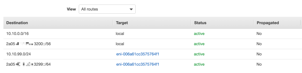
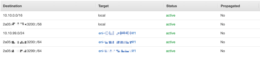
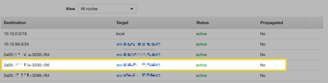
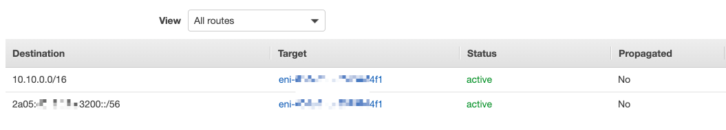
I have enabled IPv6 on the VPC (/56) and Public subnet (/64) and Private subnet (A different /64 subnet from the main /56). I have also allocated IPv6 to the ec2 instance WAN and LAN network interface. I then used /ipv6 dhcp-client on the WAN and LAN (Add default route is disabled on LAN) interface and the IPv6 address’ shown in the AWS console for the CHR instance are shown. I can ping IPv6 addresses out from CHR and remote IPv6 devices can ping the Mikrotik over IPv6

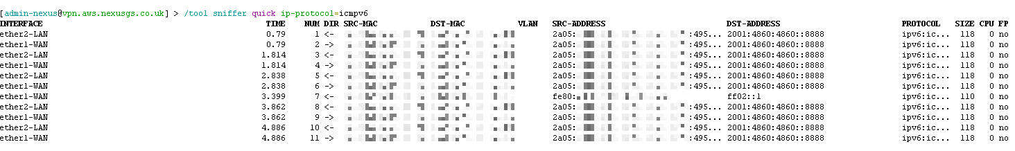
The server behind the CHR has both the correct IP4 and IP6 addresses. I can ping the CHR’s LAN IPv6 address from the server. However, when I ping6 2001:4860:4860::8888 from the server there is no reply.

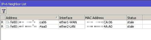
If I run torch on the LAN interface of the CHR I can see the ICMPv6 connection coming in so I know the route table in AWS is correct and if I run torch on the WAN interface I can see the response from the google server with the destination of the Linux servers IPv6 address but for some reason, it’s not making it back to the link server. I can also ping the linux’s IPv6 address from CHR.

In the IPv6 forward table, none of the drop rules are getting being hit.

The only thing I can see is on the Linux server, the ipv6 address has /128 at the end. The mikrotik has a /64

Any ideas? Many thanks for your assistance

I’ve performed a packet capture on CHR whilst pinging 2001:4860:4860::8888 from the link server and opened it up in wireshark

I can see the icpmv6 packets going from the server’s ip6 address but it says:

ICMPv6 118 Echo (ping) request id=0x10fb, seq=4, hop limit=64 (no response found!)

I am also seeing the following from the chr’s LAN ipv6 address to the servers ipv6 address with error:

ICMPv6 166 Destination Unreachable (Address unreachable)

I’ve clearly got something very wrong.

Scratch the previous post, the ipv6 route out on when I did the pcap was down at the time. Once that was working again I re-ran the test. I can only see the outbound connection, this time.

I’ve also realised the error of my ways. As the server’s ipv6 subnet is not allocated to the public subnet of the chr the reply packet will never reach the router.

I need to completely rethink how the server gets it ipv6 address allocated. Any ideas would be appreciated.

I’ve tried using prefix within the ipv6 dhcp-client to add the /64 to a pool, when I do this the status is stuck at searching.

Anyone have any ideas? Thanks

The usual concept is that you get a /48 (or /56) from your uplink provider to your border router, and delegate parts of it from there to other routers in your network, to which end devices are connected. If the prefix assignment from the uplink is static, you configure everything by hand; if you receive the prefix using DHCPv6, you configure a name of the ip6 pool to be dynamically created when a DHCPv6 client receives a prefix assignment from the server, and use that pool to further delegate prefixes. In this case, if you want to assign global (“public”) addresses manually, you specify the host part (like ::1/64) and the pool from which the prefix shall be taken. The DHCPv6 server of RouterOS currently only delegates prefixes, not individual addresses, so end devices have to use SLAAC to allocate their global addresses.

So if your /56 prefix is a static one (in terms that it does not change throughout the life of the VPC), I’d start from a completely static IPv6 configuration on the CHR as you did, because the DHCPv6 server of RouterOS is of no use for end system DHCPv6 clients anyway. So set up a your:lan:pfx::1/64 on the LAN interface of the CHR, and configure SLAAC on the LAN host (the “server” as you call it in your OP). Since by default RouterOS behaves as a router, it will multicast router advertisements on the LAN interface, so the LAN hosts should compose their complete IPv6 addresses from the prefix advertised in the router advertisement and their modified MAC address.

Once this works, you should be able to ping the LAN hosts from the CHR using their global addresses and vice versa (you may need to use ping6 on the LAN host depending on the operating system).

The next step is to add a route to 2000::/3 via the link-local address of the WAN router which you determine using /ipv6 neighbor print:

[me@myTik] > /ipv6 neighbor print where router
Flags: R - router
0 R address=fe80::5ef3:fcff:feed:8b7a interface=your-wan-interface-name mac-address=5C:F3:FC:ED:8B:7A status=“stale”
[me@myTik] > /ipv6 route add dst-address=2000::/3 gateway=fe80::5ef3:fcff:feed:8b7a%your-wan-interface-name

Notably, from the RouterOS perspective, there is no need to have any global IPv6 address assigned to the WAN interface; even if you do assign a global IPv6 address to the WAN, you still need to know the IPv6 address of the gateway to create the route, you just don’t need the %your-wan-interface-name part if the address of the gateway is a global one within the WAN’s /64, and you waste the whole /64 for a connection subnet this way.

What you do need, though, is to tell the VPC to route traffic for your /56 via your CHR’s WAN interface, so you have to determine CHR’s own link-local address and use it as a gateway in the VPC routing table, or use global addresses from the same /64 for both.

Hi Sindy,

Thanks as always for your input.

I’m guessing your advice is IPv6 generic and not directly related to how it works with AWS? Please correct me if I’m wrong.

Let me summarise a little bit on what I know:

  1. You can only allocate a /56 to the VPC
  2. You can only allocate a single /64 to the subnet
  3. When you create a VM you can automatically allocate a single IPv6 address to the interface or manually set it within the AWS console
  4. When you use /ipv6 dhcp-client and request an address on that interface on the CHR you get the single IPv6 address as seen in the AWS console
  5. If you request a prefix, you get nothing, it’s just stuck at searching
  6. If you request an ip6 address with /ipv6 dhcp-client and you look in /ipv6 neighbor you see the router address.
  7. If you remove the IPv6 address from the interface within the AWS console the neighbor disappears, even if you manually add an IP address to the interface
  8. If I statically assign an IPv6 address to the LAN interface on the CHR and use the gateway address that was discovered when using dhcp-client Ican’t ping out to the internet

I’m happy to spend more time working this out but I’m concerned that the way AWS implement IPv6 is more just for assigning single addresses to a VM as required and that this scenario is not even possible.

If any one has any direct experience with AWS’ IPv6 implementation and know if this is even possible with them, that would be appreciated.

Emphasizing this just for anyone else willing to help.


Correct. No experience with AWS, let alone EC2 in particular. But since this is a Mikrotik forum, I’ve tried to help on the Mikrotik part :slight_smile:


From your points above, it seems that DHCP is the way how AWS actually delivers the configured address to the VM(s); if this is the case, it is very likely that it also indicates the gateway address this way, so it should be sufficient to set add-default-route to yes on the /ipv6 dhcp-client row, so copying the address from the /ipv6 neighbor list would not be necessary. It also implies that one of the /64 has to be spent on linking the CHR to the outside world.

So what remains is the internet → VPC routing and delegation of the prefix to the LAN side of the CHR.

To me, Step 2: Configure a public subnet in this Amazon document, in particular the route list shown in point 5. of that Step, suggests that you can send the whole /56 to your CHR’s WAN, not just a single /64. This is the essential moment - if this doesn’t work (in either direction), you cannot use any of the VMs as a router. To test, it should be enough to assign an address from another /64 within the /56 to the LAN interface of the CHR, and specify that address a source one of a ping to some IPv6 address in the internet using src-address parameter of the ping command. This way, you can test the backward route without need to include the LAN client into the chain.

If the pings get responded both without the src-address (so using the WAN IPv6) and with it (so using the LAN one), the backward route to the whole /56 in the Custom route table works; if they don’t, it’s probably the end of the road.

If it works, you can use a script to create and maintain the /ipv6 pool row(s) using the /56 prefix of the WAN address, to which you’ll link the LAN IPv6 of the CHR.

Hi Sindy,

I’m very appreciative of your help, even if it’s just from the Mikrotik side. Just trying to work out if I’m wasting my time with the AWS side.

When using dhcp-client, the gateway is not an address out of the pool at all:

IPv6 address allocated via DHCP is in the range of 2a05:d018:xxxxxxxx

The gateway allocated and used by the default route is fe80::430:xxxxxxxxxx%ether1-WAN which I can’t even ping when using DHCP, however, the route table does say it’s reachable.

If I forget DHCP and manually set the exact same details as given by DHCP I can ping out to 2001:4860:4860::8888, however, if I change the IP address on the interface by one number at the very end e.g.:94a6/64 (as allocated on the AWS ec2 portal) to :94a7/64 the ping out no longer works.

It seems to me that AWS only routes the single IPv6 address allocated on the AWS console to that VM.

My gut instinct is that what I’m after will not be possible.

Appreciate your thoughts on this.

fe80::430:xxxxxxxxxx%ether1-WAN is link local address and it should be reachable unless blocked by service provider.
You can always disable “add-default-route” in dhcp settings and add static one.

As @mrz wrote, fe80:what:ever:: are link-local addresses, which by definition do not fit into the global IP address range, and it is nothing unusual that a default gateway’s IP address is a link-local one.


I’d say you need to follow this document, which explains how to associate your own routing table to the internet gateway, to be used for incoming (internet->VPC) traffic. This way, it should be possible to send everything that comes from the internet towards your:ipv6:pfx::/56 to the CHR’s WAN. So you’ll have one custom routing table used for the VPC (specifically, CHR WAN) → internet direction, and another custom routing table used for the internet → VPC direction.

Hi Sindy,

Thanks again, yes, that link helped, it was different to what I expected. The CHR has DHCP on both the WAN and LAN interface to get the IPv6 address allocated by AWS. The server also gets the IPv6 address allocated in the AWS console. The CHR is doing none of the IPv6 address assignment.

I feel a bit closer now but not quite there. Here is where I am now:

  • CHR can ping to 2001:4860:4860::8888 ok
  • CHR can ping server on it’s IPv6 address
  • Server can ping CHR on it’s IPv6 address
  • If server pings 2001:4860:4860::8888 there is no response but:
  • If I torch the LAN interface on the CHR I can see the ping come from the severs IPv6 address to 2001:4860:4860::8888
  • If I torch the WAN interface on the CHR I can see the ping returning back from 2001:4860:4860::8888 to the servers IPv6 address

It would suggest now that the Mikrotik is receiving the traffic back for the LAN/Servers subnet but is not passing the packet back to the server.

The route table on the CHR has both IPv6 subnets and this is confirmed as working as the CHR can ping the server ok and visa versa.

Wireshark still shows ICMPv6 118 Echo (ping) request id=0x133c, seq=4, hop limit=64 (no response found!)

Thanks again

Well, I’m not sure you actually need the AWS to assign addresses to the LAN of the CHR and to the server in the target state - I suppose you want the CHR to be the router for all other VMs within the VPC and the router provided by AWS is just something you cannot get rid of between CHR’s WAN and the internet. So once you’ve finally managed to send the traffic for the whole /56 to CHR’s WAN, there should be no need to have the CHR’s LAN and server’s eth0 connected to the AWS’ router, unless the AWS doesn’t allow to have a mere L2 transparency between VMs within the VPC. If it allows that, you can assign to CHR’s LAN a /64 address from any other /64 within the /56 than the one used at WAN, and let the server choose its EIU-64 address via SLAAC (or assign the address manually if you want it to “look nice”).


I assume you can also see the ping request from the server to 2001:4860:4860::8888 on CHR’s WAN, correct? If not, it would mean that the server->Google DNS request takes another route, but in that cause it should not be visible at CHR’s LAN either.

Other than that, I strongly recommend /tool sniffer quick ip-protocol=icmpv6 (on command line) instead of /tool torch.


Do you have anything in /ipv6 firewall export?
What does /ipv6 neighbor print say?


Wireshark on the server you mean? That’s no surprise as it doesn’t get the response :slight_smile:

I’ve created the route table in AWS and pointed the LAN subnet to the network interface of the CHR’s WAN. This route table is associated to the AWS’s IGW
2020-07-15 at 21.15.png
This is what is described here https://docs.aws.amazon.com/vpc/latest/userguide/route-table-options.html#route-tables-appliance-routing, if you see the diagram just before “Routing using a prefix list” section. It shows how you tell AWS to route the traffic.

Sniffer shows:
2020-07-15 at 21.10.png
Discovery shows:
2020-07-15 at 21.12.png
The packet capture was from the CHR, not the server

Firewall is as follows:

/ipv6 firewall address-list
add address=2a04:xxxxxx::/64 comment="Office" list=remote
add address=fe80::/16 comment="Link Local" list=allowed
add address=ff02::/16 comment=Multicast list=allowed
add address=2a05:xxxxxxxx:3299::/64 comment="AWS LAN" list=allowed
/ipv6 firewall filter
add action=accept chain=input comment="INPUT: Allow EST/REL" connection-state=established,related
add action=drop chain=input comment="INPUT: Drop Invalid" connection-state=invalid
add action=accept chain=input comment="INPUT: Accept ICMPv6 from anywhere" protocol=icmpv6
add action=accept chain=input comment="defconf: accept UDP traceroute" port=33434-33534 protocol=udp
add action=accept chain=input comment="accept DHCPv6-Client prefix delegation." dst-port=546 protocol=udp src-address=fe80::/16
add action=drop chain=input comment="INPUT: Drop Link Local from WAN" in-interface=ether1-WAN log=yes log-prefix=dropLL_from_public src-address=fe80::/16
add action=accept chain=input comment="INPUT: Allow Management from Remote" dst-port=22,8291 protocol=tcp src-address-list=remote
add action=drop chain=input comment="INPUT: Drop all other"
add action=accept chain=forward comment="FWD: Accept EST/REL" connection-state=established,related
add action=drop chain=forward comment="FWD: Drop Invalid" connection-state=invalid
add action=accept chain=forward comment="FWD: Allow ICMPv6" protocol=icmpv6
add action=accept chain=forward comment="FWD: Allow incoming from LAN" in-interface=ether2-LAN src-address-list=allowed
add action=drop chain=forward comment="FWD: Drop everything else"

That’s why I don’t like /tool torch, its understanding of send and receive is hard to understand, /tool sniffer quick shows things much better. The problem with sniffing to a .pcap file is that interface names and packet directions are lost.

So your sniff result shows that the packets from the server get received at CHR LAN and get sent at CHR WAN, but the responses do not come to CHR WAN.

The picture you refer to suggests that there is actually no LAN link between the “Appliance” (the CHR) and the Subnet B - the Applicance works as a “router on a stick” with just a single interface:

  • the packets from the server go to Amazon’s virtual router (using the default gateway obtained using DHCPv6 along with an IP address from Subnet B), which sends them to the Appliance’s WAN (eni-11223344556677889) thanks to Route table C; the Appliance has a default route to Amazon’s virtual router, also obtained via DHCPv6 along with the IP address from Subnet A, so it loops the packets received from the server for destination addresses in the internet back out through its WAN, and Route table B sends them to the internet via igw if their destination IP does not fit into the /56 assigned to you, or to the Amazon’s virtual router (“local”) if it does.
  • the packets from the internet towards Subnet B (the server’s IP) are also sent to Appliance’s WAN (eni-11223344556677889), this time thanks to Route table A, and the Appliance loops also these packets back out via WAN, and Route table B on Amazon’s router sends them to the server this time because their destination address fits into your /56 so the destination is sought among known /64 subnets (and it happens to be in subnet B).

To make the picture even more confusing, the /64 in Subnet B (2001:db8:****abcd:aa00::/64) is not a subnet of the /56 assigned by AWS (2001:db8:****1234:1a00::/56) but a subnet you’ve brought from outside, but it must work with a /64 from within the AWS-assigned /56 as well.

Since you can send packets from server to CHR via the LAN, it seems that such setup is possible too (and the default route on the server must be set to CHR’s LAN IP, not the one provided by the DHCPv6, otherwise you wouldn’t see the packets on the CHR’s LAN). But there is a small chance that they do some cross-check, so when there is no route from via the CHR WAN in the Route table associated to Subnet B (your CHR LAN subnet), packets with source addresses from Subnet B are dropped if sent from CHR WAN.

Hence I’d first double-check Route table A where a route to the LAN /64 via CHR’s WAN (eni-11223344556677889) must exist. Then, you may want to ping some external IPv6 system where you can check that the ping requests arrive instead of Google DNS, to see in which direction it actually breaks (or vice versa, ping from an external device the WAN IP of the CHR and then the server’s IP).

Hi Sindy,

Sorry for the delay, been a busy few days, so yes, I think it’s already like that, here is the route table:
2020-07-18 at 07.56.png
3200::/64 is the WAN subnet
3299::/64 is the LAN subnet
eni-xx4f1 is the network is the CHR’s WAN network interface

I have then associated the route table to the IGW of the VPC though what is known as an “Edge Association”. This page says the following which is what I think I need:

Edge association - A route table that you use to route inbound VPC traffic to an appliance. You associate a route table with the internet gateway or virtual private gateway, and specify the network interface of your appliance as the target for VPC traffic.

https://docs.aws.amazon.com/vpc/latest/userguide/VPC_Route_Tables.html
https://docs.aws.amazon.com/vpc/latest/userguide/WorkWithRouteTables.html#associate-route-table-gateway

I’ve also tried routing the entire /56 to the eni but that seems to make no difference:
2020-07-18 at 08.11.png
https://docs.aws.amazon.com/vpc/latest/userguide/VPC_Route_Tables.html#gateway-route-table

I finally sent down to routing all ip4 and ip5 /16 and /56 to the ENI. I disassociated and re-associated the the table to the IGW. Still no luck and the sniff looks the same:
2020-07-18 at 08.16.png
I then took another avenue. AWS has something called VPC flow logs which is essentially a packet trace at the VPC level and it’s split up by interface. When pinging from the server I can look at the logs for the LAN interface which shows a packet from the servers ipv6 address to the CHR’s LAN IPv6 address. But when I look at the WAN interface I can’t see any IPv6 traffic. If I ping from the CHR out I can see the IPV6 traffic ok.

If I’m reading the flow logs correctly it would suggest the ping is coming in from the server but never actually leaving the CHR’s WAN interface

…but at the same time, the ping is shown as leaving the CHR’s WAN interface when you sniff at the CHR itself. So this suggests that traffic with “wrong” source address (not associated to the eni) is blocked by AWS. However, if it was always the case, their suggested setup with router-on-a-stick would not work either, unless there is some hidden dependency, which e.g. makes source addresses belonging to Subnet B “legal” on eni-11223344556677889 if there is a route via eni-11223344556677889 in the Route table associated to Subnet B.

I’ve gone as far as to create a free account on AWS, but they want a credit card number even though the account is free, so I’ve stopped at that point for now. And I’m not even sure you can “bring your own disk image” to a free EC2 account.