CSS326-24G-2S+ to CSS326-24G-2S+ Vlan problems on 2nd switch for Linux

so ive had a couple topics but i recently found there is still a problem i guess the vlans and plain Vlan 1 isnt working right

the vlans and just default Lan .. do not work with Linux the dhcp can not give the network cards an ip address. if i set the ip address then it will work.. but dhcp doesnt having issues with unraid… and where a ethernet wont get an ip but the 10g fiber can but only in a certain configuration.. other then a new default it cant get the default vlan1 on a 10 g card

Windows Laptop has 0 issue on the 2nd network switch getting a Vlan 1 10 20 30 40… you plug into a port it gets an ip address no problem… you plug the linux server in the same port no ip just a 169.. ive done a new install and still cant get an ip address.. through linux

now i was reading more that for the rtsp root i guess you want it on your Router.. not switch to switch port.. i cant seem to get the root desginate to go on my pfsense router port.. i did kinda get the root bridge at a 0000 for the pfsense router… but i dont see a root to force it on the router … so i guessing i getting a round robin error probably something i read that it circles… if i set the root bridge back to default 8000 to all of them.. the switch 1 points to 2nd mikrotik switch as room cost 19.. i can not get that to goto pfsense

here is what i got on switch 1.. and the port that says to “the house rack” thats the 2nd mikrotik switch.. now i dont have issues going from mikrotik on switch 1 to a 10g switch and then to a cisco … but it seems down hill on switch 2 anything behind it.. that is linux cant get a ip unless you static or if its windows it works fine… so i hoping you guys know how to fix this i thinining i should never got 2 of these switchs but a router switch where you can set it to trunk to the switchs you want

and i tried playing with the 4096 0000 8192 for the bridge root settings but if you checking boxes etc how can you see what port has witch root bridge value? that like ports 1 -5 have 4096 0000 is on port sftp2 8192 be on a couple other ports

how you see those values?

but here is switch 1

and sorry if i didnt explain as i got dislexia and learning disablity so i dont explain things right so i hope i did

switch 1 here is no issues for other switchs and dhcp on linux boxes

switch 2 is where i have problems dhcp doesnt work on linux boxes but will work on windows boxes

i not sure if windows does something special to get vlans and regular main vlan1 to work

and there is no real video or explanation scenarios on this switch mostly for routeros but not switchos and this specific model.. to get it to work.. so you still gotta be smart at understanding it

First question, before diving in too deep: Have you actually configured a vLAN1? Because vLAN1 is the default and you should not configure anything for vLAN1. vLAN1 exists on Mikrotik to allow external untagged non-vLAN traffic to be managed internally within the switch or router consistent with vLAN traffic. It has no other purpose.

no i havent well not true cuz i was also trying vlan1 to see if it would work as i been setting tagged untagged any force vlan id etc

but not from the pic above no its set to n vlan ill post newer pics.. i didnt notice an issue before i guess cuz windows dhcp receiving is simplier where linux is more complex and its hit and miss when it works etc…

so like on switch 2 goes into couple other switchs and AP and and works for a raspberry pi.. but it doesnt work for unraid linux box and the 10gig fiber card works in some configuration i have but if you do a new install of unraid server.. it cant get a dhcp
google AI talks about setups this switch cant do when i google this switch… and says linux uses a different way then windows uses dhcp … and i am able to WOL the unraid box from pfsense on switch 1… but it can not get a ip address

so if you do configure vlan1 1.. why does it allow you do it? 2nd what happens when you do configure it.. does it glitch the switch?

so here is the switch 1.. it comes from pfsense router and goes to other switchs and devices.. i tried to get pfsense to show root and cost 19 under rtsp i couldnt… i could only get mik switch to mikswitch to go root

now i dont even understand with the root bridge if i set it 0000 for pfsense port then it doesnt add root 19 cost it deletes from mik “to house rack” yet doesnt add it to the pfsense so that all confuses me

but here is switch 1

here is switch 2

and before i bought the 2nd css326 switch a while back… i had a dumb switch un managed and i didnt have problems coming from switch 1 the css326 switch.. but when i expanded to iot and camera i went with a 2nd css326 to get vlans to expand and seperate to there own networks

and the management port vlan i use that for incase my 10g nics stop working on the default lan 192.168.0.x
the management port is vlan30 192.168.30.x connected to the onboard motherboard nics so i have still a backdoor hopefully… but i find

default lan 192.168.0.1 doesnt work for the backup server if i do a fresh install or delete config file its hit and miss.. even for default lan

but windows no issues on anything so thats why i truly didnt see this problem a while ago.. it just works

I agree you need to understand.

There are some youtube videos, but no high quality professional grade ones that I am aware of.
Wilmer Almazan / The Network Trip has a playlist with a video that was planned but never released. It would have been good. https://www.youtube.com/playlist?list=PLNRJTwfzNNlb-k6D2tYTSVGccfOegWMYO

Mikrotik switchOS configuration: a step-by-step guide | VLAN tagging/port separation is for the switch you have. By TimiGate. It isn't a tutorial; it is more like a show and tell to a friend; a walkthrough without many explanations as to why. For example he doesn't discuss VLAN mode.

I think the best documenation is the what I stated in your other thread

But you have posted a lot of text, but not given some of the most important info.

How are things connected? Don't expect the people you want help from to spend excessive time to try to figure this out. A diagram is worth a lot in transferring information quickly. Even a photo of a hand drawn sketch is much better than trying to extract it from all the text in your threads. Having the screen shots is nice to be able to verify things, but not a good source of info for the "high level overview" context.

The diagram needs to show any links that need to carry more than one vlan; i.e. any links between the switches (all of them, you mention the two CSS326 switches, but also a 10G switch and a cisco switch). We need to know how these are connected. And if there are any loops, that's where RSTP comes into play. Note that the mesh wifi can act as an alternate path, and lead to loops.

Most importand things to show us on the diagram.

  1. How the pfSense router is connected (I think with a trunk link to SW1 port 26 (SFP2). What subnets are defined on the pfSense router? What interfaces are defined? How do the subnets map to the interfaces? How are the vlans defined? Is anything untagged. (If you plug a PC into the pfsense port that is connected to the switch, does it get a dhcp address? Is it consistent?
  2. All the connections to the other switches since these probably need to be trunk links.
  3. All the connections to AP's (since these may be carrying multiple vlans).
  4. An example of a port that works for both Windows dhcp and Linux dhcp.
  5. An example of a port that works for Windows dhcp but not linux.
  6. Any other thinks that don't work as you expected, and what you expected. Also copies of the errors you get.

Things covered here: https://jdebp.uk/FGA/problem-report-standard-litany.html

Things covered here: https://www.chiark.greenend.org.uk/~sgtatham/bugs.html

and i thought i explaioned it

anything directly connected to switch 2 mikrotik if your a linux machine doesnt work

everything else works fine stupid dislexia

i think i got all the info in the drawing if i missed something let me know

so vlan 30 ,default

mik switch 1 ====> server 1

cisco router ====> server 2

these both work

but from Mik Switch 2 directly a PC running linux default doesnt work.. just Static IPs

ill try today to take backup server from Mik2 switch and put it on the Switch 1

4.. example of por that works for both windows and Linux Everything under Mik1 switch

  1. example of port that works for windows but not linux = everything under Mik2 switch topology intis includes Camera or IOT or any port

so i hope i answered best i can ill take at those links now here is the pic

and i read you watch to set switch to tagged if you trunking 1 switch to the other from the google ai for mikswitch well when you do that only tagged it blocks all access to the 2nd switch

so to sum up what i orginally said

everyting under Mik switch 2 doesnt work for linux, everything under mik switch 1 works for linux

now i havent tested multiple linuxs since Raspberry Pi has no problem getting an IP

but no unraid server can get an ip unless i can static the ip.. and dhcp works for the 10gig sfp if i change the network rules.cfg file a clean install doesnt work but the backup rules works but only for the 10g sfp it still unable to get for the vlan 30

on the backup server where currently 10g seems to get ip but if you install a fresh linux it cant get an ip

and no matter what the onboard card cant get an ip unless you static

network.cfg


# Generated settings:
IFNAME[0]="br0"
DHCP_KEEPRESOLV="no"
DHCP6_KEEPRESOLV="no"
BRNAME[0]="br0"
BRNICS[0]="eth0"
BRSTP[0]="no"
BRFD[0]="0"
DESCRIPTION[0]="10gig Nic Main"
PROTOCOL[0]="ipv4"
USE_DHCP[0]="yes"
USE_DHCP6[0]="yes"
VLANID[0,1]="10"
DESCRIPTION[0,1]="Cameras"
PROTOCOL[0,1]="ipv4"
USE_DHCP[0,1]="yes"
METRIC[0,1]="0"
VLANID[0,2]="20"
DESCRIPTION[0,2]="IoT Devices"
PROTOCOL[0,2]="ipv4"
USE_DHCP[0,2]="yes"
METRIC[0,2]="0"
VLANID[0,3]="40"
DESCRIPTION[0,3]="DMZ"
PROTOCOL[0,3]="ipv4"
USE_DHCP[0,3]="yes"
METRIC[0,3]="0"
VLANS[0]="4"
IFNAME[1]="eth1"
DESCRIPTION[1]="Management Port"
PROTOCOL[1]="ipv4"
USE_DHCP[1]="yes"
USE_GW4[1]="on"
SYSNICS="2"

network-rules.cfg


  GNU nano 8.6                                                    network-rules.cfg                                                               
# PCI device 0x10ec:0x8168 (r8169)
SUBSYSTEM=="net", ACTION=="add", DRIVERS=="?*", ATTR{address}=="f0:2f:74:53:3f:11", ATTR{dev_id}=="0x0", ATTR{type}=="1", KERNEL=="eth*", NAME="eth1"

# PCI device 0x8086:0x1557 (ixgbe)
SUBSYSTEM=="net", ACTION=="add", DRIVERS=="?*", ATTR{address}=="98:b7:85:20:0b:b6", ATTR{dev_id}=="0x0", ATTR{type}=="1", KERNEL=="eth*", NAME="eth0"


hope all this helps

i havent tried the backup server on switch 1 yest since its a several hundred pounds and is more then 500 feet away where i wanna plug it in..

but question in the bios of motherboards.. its an Asus TUF GAMING X570-PLUS (WI-FI)

is there a BIOS option that disables dhcp to work correctly? maybe the switchs are working fine its just a bios feature??

does the other os or windows os setting in bios cause issues? for the boot that causes dhcp issues?

I have no experience with unraid or the Asus TUF GAMING X570-PLUS (WI-FI)

however, my guess it that it is a problem with the unraid box, not linux in general.

Because you have multiple interfaces defined, what does the routing table look like on the unraid server?

can you run the following on the unraid from a command prompt?

ip addr
ip route
ip route get 8.8.8.8

It will show interfaces with ip, the routing table, and what default gateway is used to get to internet.

@comet424 you are using vlan 1. If your non-vlan aware devices are connecting to ports where "default vlan" is set to 1, my guess is they are getting an IP address from 192.168.0.0/24.

ethernet frames that don't have a specific tag will use the pvid (what SwOS calls default vlan) to select which vlan the receiving switch will classify the frame to use.

Because you are using optional for VLAN mode, there is no check to verify that the port is a member of the vlan. This is the "out of the box" config, but that is to allow the switch to behave similar to a "dumb switch" until manually configured. Although, normally all ports are set to have default vlan set to 1, and vlan mode is optional and receive frame is all. This will allow the use of tagged frames (for vlans other than what the default vlan is set to), an the frames will be retransmitted with the same tag on egress (when in factory reset condition).

In a "correctly configured" SwOS switch, the ports have "strict" set as VLAN mode, to enforce port vlan membership. But then that requires configuring the VLANS tab with all used vlans and the ports that are members.

Your switches are "almost" like dumb switches. with the exception of ports in the VLAN tab where you have set default vlan to something other than 1 (or the VLAN receive to something other than "any")

ok so for your 2 replys
first the ip addr etc

results

root@backupserver:~# ip addr
ip route
ip route get 8.8.8.8
1: lo: <LOOPBACK,UP,LOWER_UP> mtu 65536 qdisc noqueue state UNKNOWN group default qlen 1000
    link/loopback 00:00:00:00:00:00 brd 00:00:00:00:00:00
    inet 127.0.0.1/8 scope host lo
       valid_lft forever preferred_lft forever
    inet6 ::1/128 scope host 
       valid_lft forever preferred_lft forever
2: tunl0@NONE: <NOARP> mtu 1480 qdisc noop state DOWN group default qlen 1000
root@backupserver:~# ip addr
1: lo: <LOOPBACK,UP,LOWER_UP> mtu 65536 qdisc noqueue state UNKNOWN group default qlen 1000
    link/loopback 00:00:00:00:00:00 brd 00:00:00:00:00:00
    inet 127.0.0.1/8 scope host lo
       valid_lft forever preferred_lft forever
    inet6 ::1/128 scope host 
       valid_lft forever preferred_lft forever
2: tunl0@NONE: <NOARP> mtu 1480 qdisc noop state DOWN group default qlen 1000
    link/ipip 0.0.0.0 brd 0.0.0.0
5: eth1: <BROADCAST,MULTICAST,UP,LOWER_UP> mtu 1500 qdisc mq state UP group default qlen 1000
    link/ether f0:2f:74:53:3f:11 brd ff:ff:ff:ff:ff:ff
    inet 169.254.237.37/16 brd 169.254.255.255 scope global noprefixroute eth1
       valid_lft forever preferred_lft forever
6: eth0: <BROADCAST,MULTICAST,UP,LOWER_UP> mtu 1500 qdisc mq master br0 state UP group default qlen 1000
    link/ether 98:b7:85:20:0b:b6 brd ff:ff:ff:ff:ff:ff
7: eth0.10@eth0: <BROADCAST,MULTICAST,UP,LOWER_UP> mtu 1500 qdisc noqueue master br0.10 state UP group default qlen 1000
    link/ether 98:b7:85:20:0b:b6 brd ff:ff:ff:ff:ff:ff
8: eth0.20@eth0: <BROADCAST,MULTICAST,UP,LOWER_UP> mtu 1500 qdisc noqueue master br0.20 state UP group default qlen 1000
    link/ether 98:b7:85:20:0b:b6 brd ff:ff:ff:ff:ff:ff
9: eth0.40@eth0: <BROADCAST,MULTICAST,UP,LOWER_UP> mtu 1500 qdisc noqueue master br0.40 state UP group default qlen 1000
    link/ether 98:b7:85:20:0b:b6 brd ff:ff:ff:ff:ff:ff
10: br0: <BROADCAST,MULTICAST,UP,LOWER_UP> mtu 1500 qdisc noqueue state UP group default qlen 1000
    link/ether 98:b7:85:20:0b:b6 brd ff:ff:ff:ff:ff:ff
    inet 192.168.0.4/24 brd 192.168.0.255 scope global dynamic noprefixroute br0
       valid_lft 6901sec preferred_lft 6001sec
11: br0.10: <BROADCAST,MULTICAST,UP,LOWER_UP> mtu 1500 qdisc noqueue state UP group default qlen 1000
    link/ether 98:b7:85:20:0b:b6 brd ff:ff:ff:ff:ff:ff
    inet 192.168.10.4/24 brd 192.168.10.255 scope global dynamic noprefixroute br0.10
       valid_lft 6908sec preferred_lft 6008sec
12: br0.20: <BROADCAST,MULTICAST,UP,LOWER_UP> mtu 1500 qdisc noqueue state UP group default qlen 1000
    link/ether 98:b7:85:20:0b:b6 brd ff:ff:ff:ff:ff:ff
    inet 192.168.20.4/24 brd 192.168.20.255 scope global dynamic noprefixroute br0.20
       valid_lft 6914sec preferred_lft 6014sec
13: br0.40: <BROADCAST,MULTICAST,UP,LOWER_UP> mtu 1500 qdisc noqueue state UP group default qlen 1000
    link/ether 98:b7:85:20:0b:b6 brd ff:ff:ff:ff:ff:ff
    inet 192.168.40.4/24 brd 192.168.40.255 scope global dynamic noprefixroute br0.40
       valid_lft 6920sec preferred_lft 6020sec
14: vhost1@eth1: <BROADCAST,MULTICAST,UP,LOWER_UP> mtu 1500 qdisc fq state UP group default qlen 500
    link/ether 02:49:41:c1:dc:6a brd ff:ff:ff:ff:ff:ff
root@backupserver:~# ip route
default via 192.168.0.1 dev br0 proto dhcp src 192.168.0.4 metric 1010 
169.254.0.0/16 dev eth1 scope link src 169.254.237.37 metric 1005 
192.168.0.0/24 dev br0 proto dhcp scope link src 192.168.0.4 metric 1010 
192.168.10.0/24 dev br0.10 proto dhcp scope link src 192.168.10.4 metric 1011 
192.168.20.0/24 dev br0.20 proto dhcp scope link src 192.168.20.4 metric 1012 
192.168.40.0/24 dev br0.40 proto dhcp scope link src 192.168.40.4 metric 1013 
root@backupserver:~# ip route get 8.8.8.8
8.8.8.8 via 192.168.0.1 dev br0 src 192.168.0.4 uid 0 
    cache 
root@backupserver:~# 

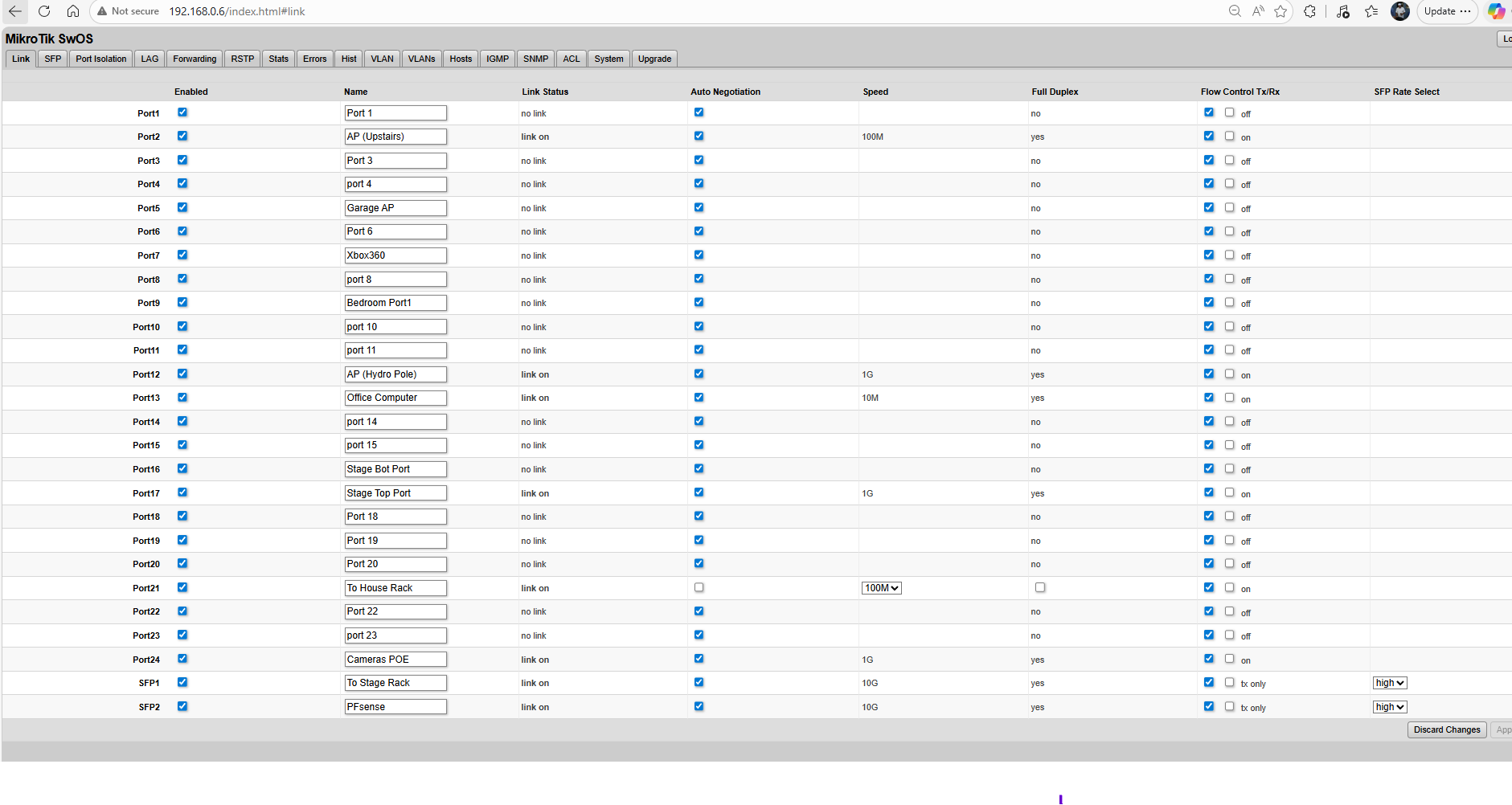
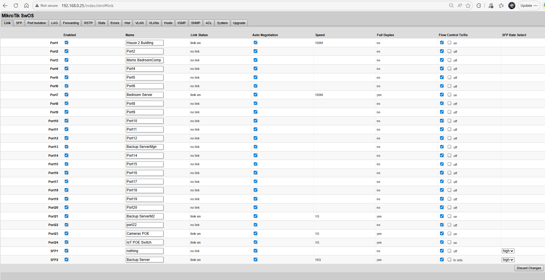
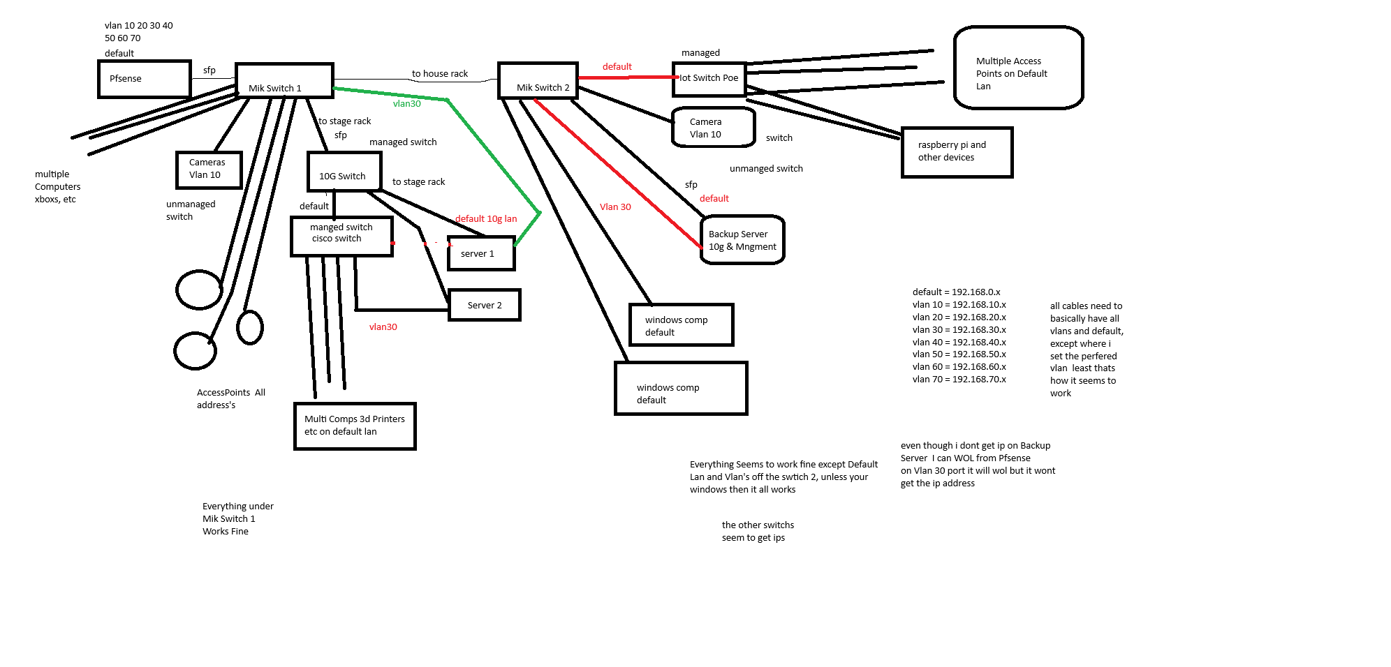
now i did bring the backupserver and i unplugged server 1 in the pic and plugged it in.. and turned on still only got a dhcp on the 10g not the realtek

now server 1 and backupserver are identical motherboards just not the cpu

server 1 can get vlan30 dhcp or vlan40 if i change it in the switch.. but doesnt work on backupserver

i did some more testing on the backup server

i ran ubuntu 20 on a bootable usb drive.. Onboard network card no ip address , 10g i got ip address on backupserver

i installed windows 10 on a ssd on backup server.. i got an ip address on onboard so 192.168.30.x but nothing for the 10g i didnt have a driver for the 10gig

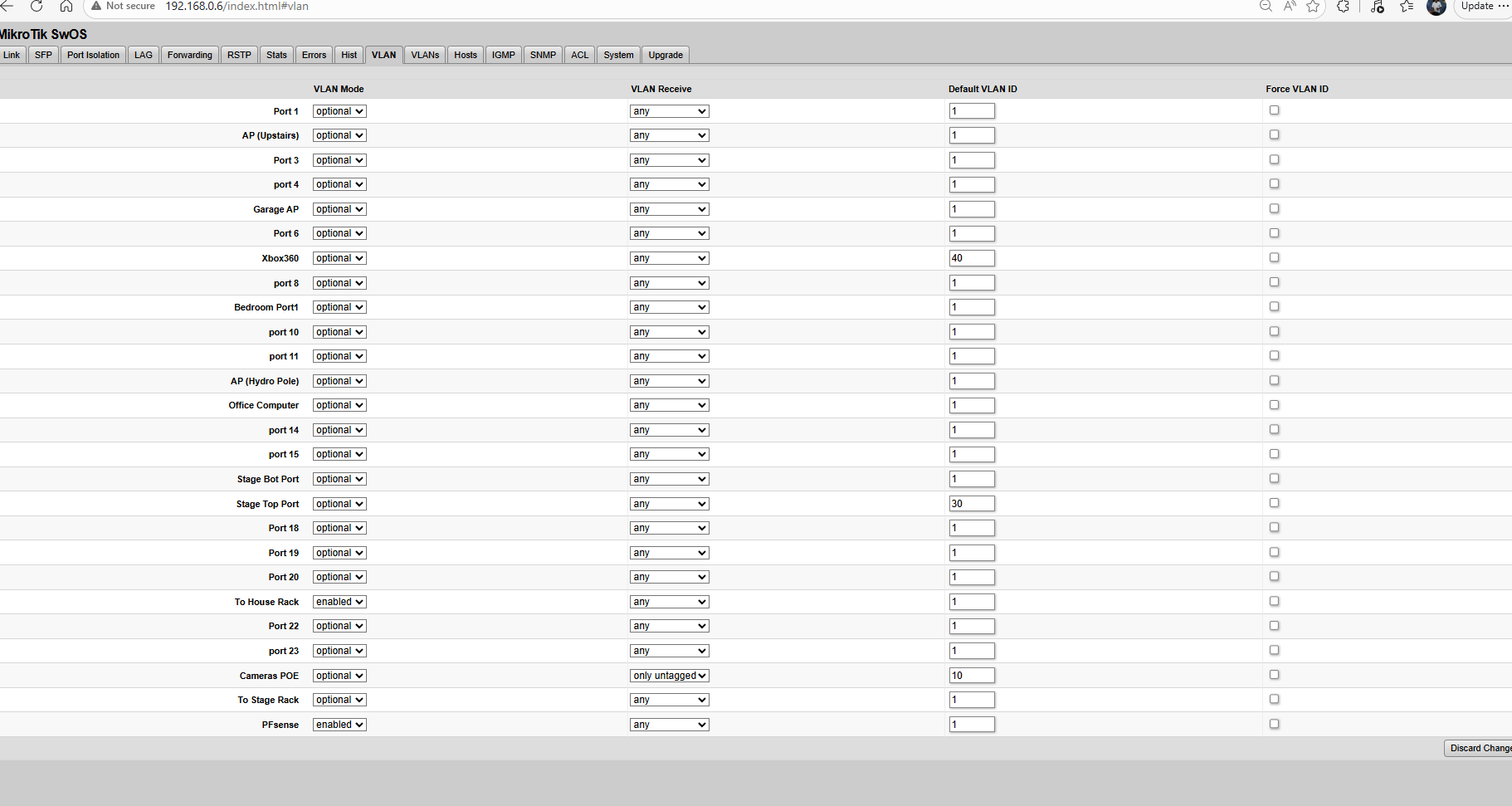
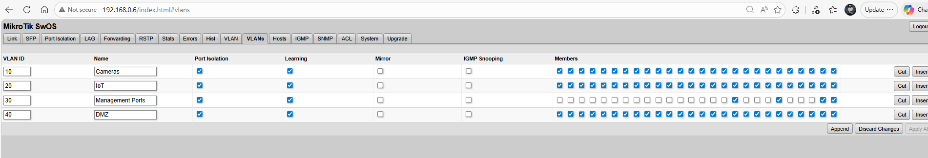
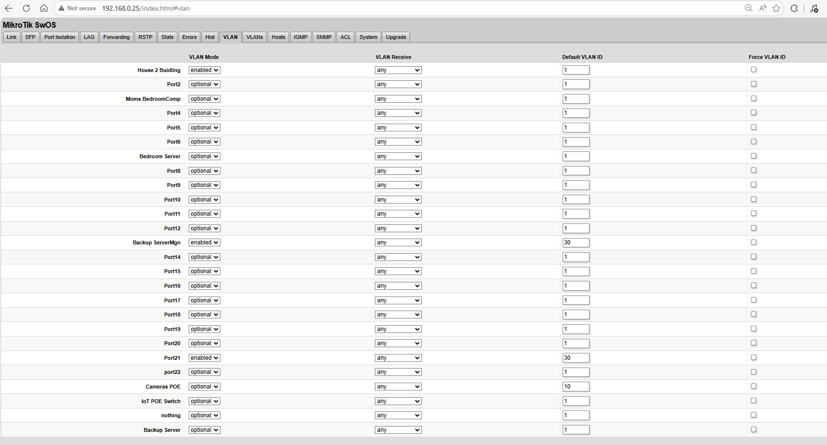
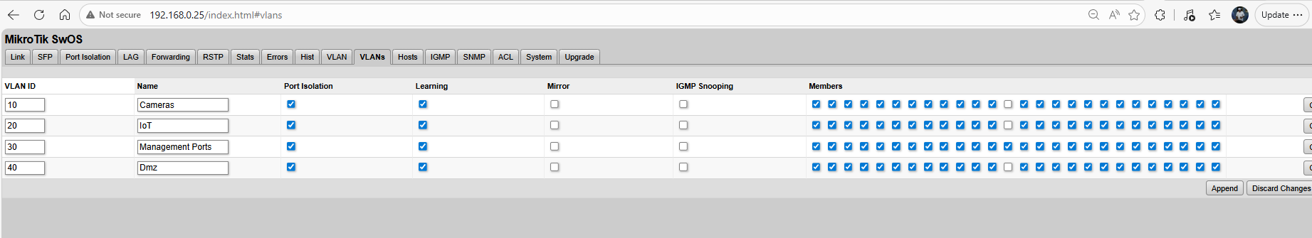
everything runs off the 192.168.0.x network except for camers they go on 192.168.10.x, IoT switch is divided from default Vlan1 to 70 so it handles it.. and then the direct connection for the servers that are set to Vlan 30 to go on the 192.168.30.x for the management port

so i have it setup so all comps will be the default.. and i just set the default vlan ID to like 30 or 40 or 10 etc and that has seemed to work for the most part

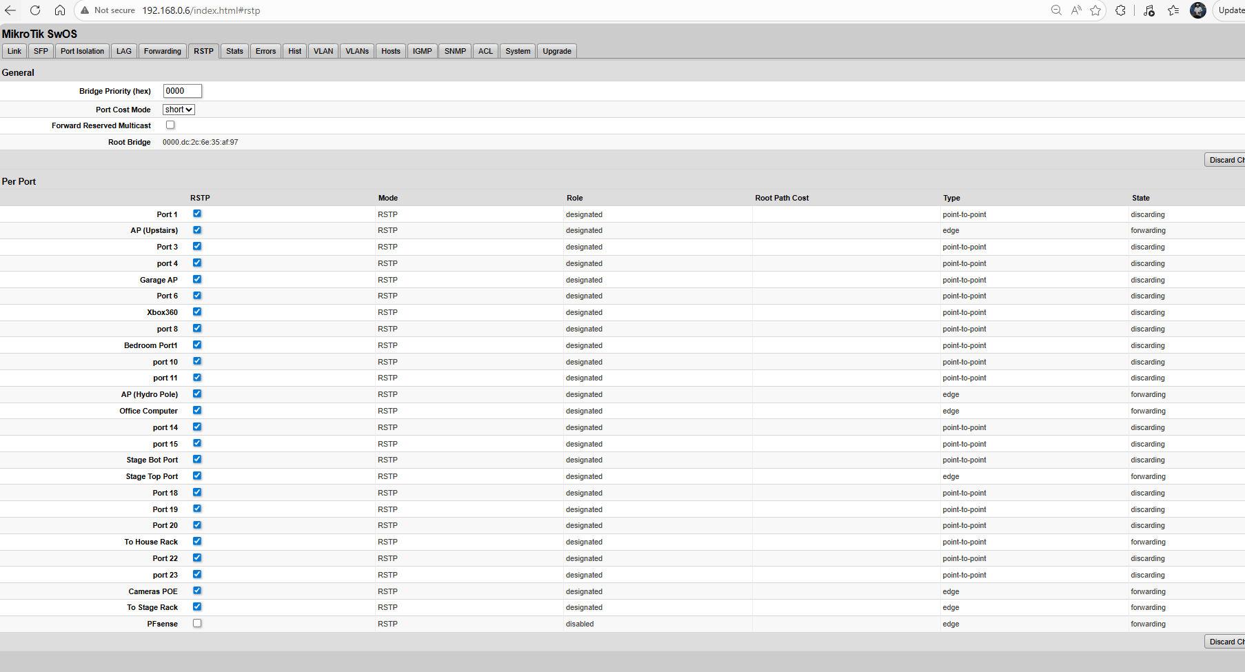
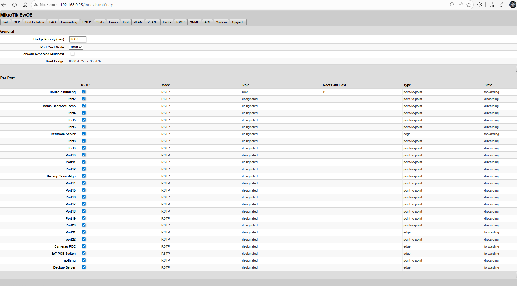
i figured i configured things wrong when i cant get “root” and “cost 19” to show up on the rtsp tab to the pfsense box.. it keeps showing up on the link to the 2nd mikrotik switch.. so figured that was the problem too..

so i did some testing

mik1

mik4

mik3

mik2

these all caused 169.x on backup server

so when i properly configure a port same cameras it should be

strit or enabled , untagged only, vlan10, and dunno if you need to check on or off a box

is that the correct way then?

i did no test ubuntu on the server 1 but the dhcp is working on it.. so my question is maybe the cpu is bad that allows dhcp? in linux since it works on server 1 but not backupserver? but dhcp works in windows 10 on the backupserver

so i confused why it works in all ways on server 1.. but not backup server they are the same board just a different cpu

another question you mention you want to set the vlan strict and tagged i guessing as i read tagged = trunk

so when you have the 2 switchs connected. together do you leave it on optional and 1 as the vlan or do you change it to strict and only tagged? as that will lock me out from the 2nd switch when i do that on the first switch..

i wonder if i re flash the bios on the backupserver comp if that will fix any glitch maybe? as i stumped on whats going on

and from trying to re read and understand since i have dislexia and learnign disability

if i leave “optional” to the other switchs cisco and 10g etc and leave it on “any” and “1” that basiclly passes all traffic vlan1 default and the vlans 10 20 etc

and if i chose “enabled” or “strict” and left it on “any” would that do any vlan except the “1”

there is a new bios update from feburary.. i going to try that to see if that fixes this glitch or issue i having

well the bios update didnt fix .. i wonder if its just a glitch in the motherboard or the cpu? thats causing it? works in windows but not ubuntu or unraid linux.. works if i static ip .. so i confused.. i thinking i gotta try a different cpu to see if it does anything but i stumpped

and could you tell me then how to properly configure the 2 switchs? from mik to mik mik to other switchs mik to ap’s

like on the cisco which the gui doesnt work anymore its failing.. and might replace it with the mik1 switch and get a better switch to replace the location of mik1 with a 10gig fiber managed switch

but on the cisco i use tagged for like vlan30 and un tagged on the port that goes from cisco to mik2

on the 1 10g switch i use tagged vlan 1-40 and i set the servers to Trunk and Desktop PCs to Access

but i gotta watch that switch video you shared i only got into it a little.. as i went to test different OSs on the that backup server comp

Don't set strict until you fix other things. you don't have vlan1 defined in the VLANS tab.

Right now every port has access to all vlans, the membership is not enforced.

If you change to strict, things will stop working because it will enforce membership.

It currently like going to Costco without a membership and walking in with someone else.

ah ok and enabled means it allows all vlans in from what i read?

i did try strict on vlan10 for the camera switch.. and that seems to work fine i got it

does strick = trunk, enabled = hybrid, or access? i wish they would only have the 3 options access,trunk,hybride.. would make things little easier when you know from 1 switch trying to learn another

so what should i have set for mik1 to mik2 switch to pass everything.. so then i can properly duplicate it

and how do you set the root and root cost to the pfsense port? since when i unchecked all those rtsp and just the pfsense and i saved and set it to 000 or 1 it erases all the rest.. i get confused on that stuff as you can i guess set 10 ports to 4096 5 or 8000 1 on 1.. but there is no list on your settings

so ya like it seems all to work but since i wanna configure this properly i could use the exact settings to pass everything to each switch.. unless optional or just enabled and “any” “1” is the proper setting

i guess ill either tackle taking the cpu out of “server 1” and swap it with backupserver today

or order another cpu for backupserver…

but ya frustrating at times never enough parts lol.. i appreciate your help so far..

What is the purpose on using vlans? It seems that as configured there is very little enforcement of separation between them.

That's all in the VLAN Configuration Example in the VLAN and VLANs section of the CRS3xx and CSS3xx series Manual - SwOS - MikroTik Documentation

You need to determine which devices are just connecting to a single vlan (and configure those ports as access ports).

Ideally you would make all your trunk links "all tagged", but you evidently currently have your pfSense box using the untagged interface (like icg0) the default "native" lan. The vlan interfaces have .10 .20 etc. after the parent interface name, e.g. icg0 would be untagged, icg0.10 would be tagged with vlan 10, icg0.30 would be tagged with vlan 30, etc. As you currently have things configured the links between the switches , vlan 1 is your "native vlan", and that is what will be used by non-vlan aware devices. (That is true for your IoT PoE switch as well, if that IoT PoE switch isn't vlan aware (have a way to configure it), then your IoT devices connected to it are probably using 192.168.0.x addresses, not 192.168.20.x as

Review https://docs.netgate.com/pfsense/en/latest/vlan/index.html

Ths VLANs and Security section discusses VLAN 1 and why it is generally recommended to avoid using it for data (i.e. what is being used for 192.168.0.0/24 on your network).

Untagged traffic on links between switches can lead to mixing if misconfigured. This is shown in the Ed's vlan challenge quiz

If you want understanding, and not just an overview, I highly recommend Ed Harmoush's Practical Networking site https://www.practicalnetworking.net Ed has recently started a Networking Fundamentals course and he is putting the first module (with multiple videos) on Youtube. It's a good intro with very little assumptions about previous knowledge. Ed has some of the best explained info about vlans Virtual Local Area Networks (VLANs) See the challenge quiz if you think you understand vlans. Ed also has a video covering the same info VLANs – the simplest explanation Here's an index to the vlan pages on PracticalNetworking

I think you are focusing on things that are very unlikely to be the cause of your problems.

For example, I can't think of a reason that the CPU in your server could be related to dhcp not working.

If if was an issue with the CPU, it would be affecting much more than just dhcp.

The rstp root bridge is another "red herring". RSTP is to prevent loops in your ethernet, if you have loops in your ethernet and RSTP isn't there, you will know there is a problem. You network will freeze because of broadcast storms (google it). That isn't the issue you are having. You can learn about that another day.

Likewise the BIOS is very unlikely to have any effect other than at boot time.

ok ill read up on that stuff

so ya vlans i configure in Pfsense and then have dhcp servers for each vlan and then i have the rules set up in pfsense what it can access etc

as for the vlans

vlan1 = desktop pcs and some tablets, and all access points so they can handle all the vlans

vlan10= POE Cameras

vlan20= Iot Devices, Wired, Wifi, 3d printers etc

vlan30 = Management port when the Vlan1 is down or the card cant be accessed so i can still access it

vlan40 = DMZ for webservers, Xboxs, and Remote Gaming

vlan50 = Guest Network

Vlan60,70 were test stuff i was playing with

all switchs, and Access Ports all need to have All the Vlans except 30 for the Access Ports so thats why i un member them from the other vlans.. as its just a hard wire and doesnt need to work on any access points

as for devices connecting to a single vlan ya i already have that in the pic you see camera poe switch gets a vlan of 10, every other switchs has to get Vlan1 default, and desktop pcs just need Access, and the Servers all get a trunk of 1-70

now the problem when i did you said all the trunk ports all tagged.. if i trunk Mik1 to Mik2 switch Switch2 is no longer accessable i loose connection

but ill re read all that info you supplied.. currently i swapping the cpus of the 2 servers.. just to see if its a cpu issue thats going on or if its a motherboard issue as i cant figure that out

but once i done ill read up on your articles you supplied and try the tagged stuff again..

i appreciate the help so far cuz i was getting frustrated and the little support videos, and i used to

as for you thinking its not a cpu i at a loss then i guess its a motherboard issue as 2 identical boards one works getting a dhcp other doesnt…

so i confused thats for sure