Hi. in our project we plan to deploy approx 60 hEX S's in indoor/outdoor installations. Some of them powered from 55 V DC, some of tem from 24 VDC. As the installation will be in country closer to the equator, the summer temperatures are expected to be around 40 deg Celsius, while in the box, they might be as high as 60deg.
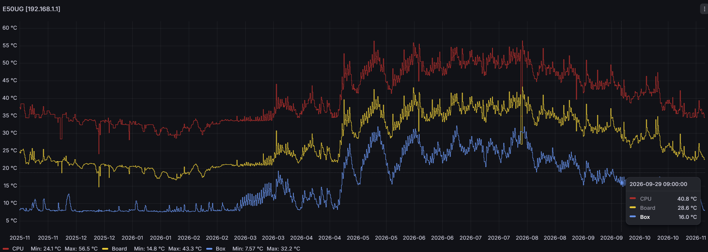
When I checked the temperature reported by the hEX, I found that units supplied from 24 VDC have reported temperature lower by 15-20 deg compared to those supplied from 55 VDC. This means that when ambient temperature is about 20deg, the reported temperature from 55 VDC is as high as 70deg (inside the box is around 30-35deg). When I touch both the 24VDC and 55VDC units, they feel the same (like 45deg).
Does somebody has similar experiences? Should I be afraid of shortened life of units when supplied from 55 VDC?
Thanks for your experiences.
PS: in this task the load of those units will be low - CPU 1-3%, so those units will be basically idling...
Hi there. That's an interesting finding - can you confirm with a thermometer at a few different places on the device: near the power connector, center of the device, back of the unit in the prolongation of the power connector? Checking both the top and bottom of the unit for each measure would be perfect.
Note that 55V is really pushing it close to its input specs. Given the wide input range, I suspect the unit uses a DC-DC converter and not a linear regulator. If that's the case, the temperature should not be super dependent on the input voltage, but you never know.
I can't on those devices (mounted on a DIN rail inside small IP box), but I will try on my own units at home inc. thermocamera, nicely side by side.
BTW I expect that those 57 VDC is something like "nominal", as POE can reach even a bit higher (such as four 12V batteries in series when charged...which is a common situation for ISP with 48V battery backup).
Surely it has inside a DC-DC buck converter (not a linear one), but the actual voltage(s) used by the board are likely to be 5V and 3.3V or so.
It is possible that the converter is more efficient (please read as less heat generated) when input is 24 V than when it is 48-55V.
If you are going to put them (at least the outdoor ones) inside a sealed (electrical) box, then you might have a problem.
Generally speaking the idea behind passively cooled devices is that by convection fresh air enters continuously from the bottom, passes through the device and exits it from the top bringing with it some of the heat produced by the device.
The moment you close the device inside a box this mechanism ceases to work properly because the air that is intaken is essentially the same that is output, at the same or at a very near high temperature (unless the box is large enough or something else cools the air, or the box is not sealed and allows external air to enter and exit it).
My personal (not necessarily right) rule of the thumb is that a device (idle or at low CPU) cannot (should not) have a temperature higher than 20-25 °C + ambient temperature, so you are roughly within that range, but "ambient" inside a sealed box may well be very different from actual "open-air" ambient, the heat can accumulate and additionally you might need to take into account the effects of the sun.
The hex S is given as "Tested ambient temperature -40°C to 70°C", which does not mean that at 71° they will melt, but surely you wil be operating them at the highest possible temperature which generally speaking is not a good idea.
Of course I look at ambient temperature as temperature inside the box, outdoor temperature is expected to be something like 40deg during summer. The box has dual wall to allow airflow while keeping IP and also help with isolation against sun irradiation.
Good, so you will be using them inside the tested temperature range.
But let's say that you have an increased ageing due to operating temperatures on the high side.
How much will it be translated into operation time?
We have an expectation (confirmed on the field by people that run these devices) of around 10 years of life (or more) operating 24/7 in "normal" environments.
Considering that you will have hot days but also relatively fresh nights, I don't believe that life of the devices can be shortened by more than half, being pessimistic.
So you could expect them to work for 5 years or so, not bad at all IMHO.
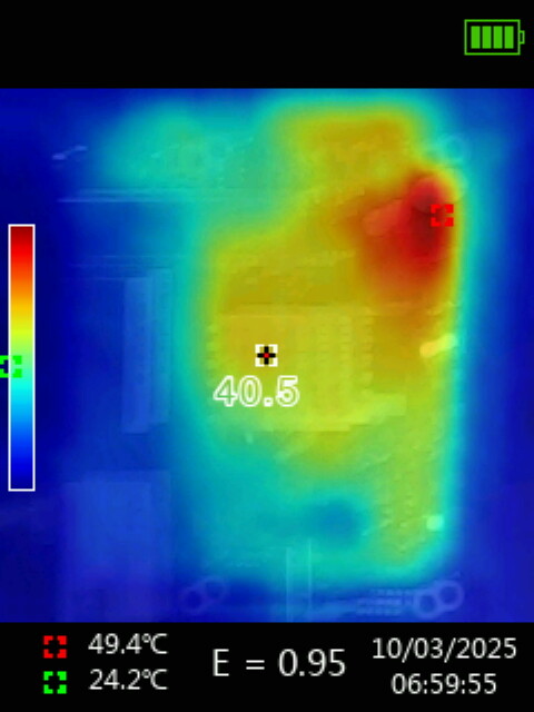
So I made the termocamera test. Power supply high was 57,5 V SNMP (56,5 V uncal DMM reading). After warm up (without the plastic case, no traffic), the reading of temp via SNMP was 21°C for 24 VDC and 38°C for 57 VDC version.
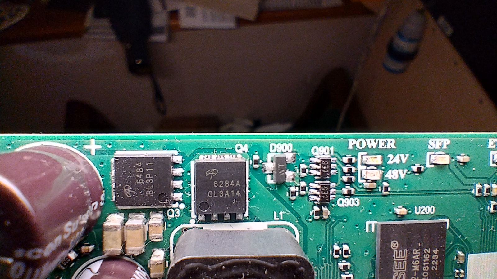
The biggest difference on the PCB was in the power supply part, namely these IC/Semconductors.
Note that the colour scale is automatic so it is different on each picture (spans between lowest and highest detected temp.)
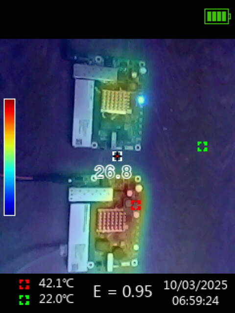
The temp pictures shows (from left) 24VDC, 57 VDC and both (57 VDC at the bottom)
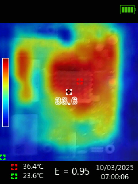
If this question was on me (otherwise sorry), you can see the coolest spot in the green bracket - ambient was around 22 deg. The colour scale spans between coolest and hottest spot (values bottom left). Hotest spot is in red brackets.
...its a cheap IR camera so its features are very limited.
Good, so the lowest in each image is the ambient.
36.4° C at 24V with a delta of 12.8°C over 23.6.
49.4° C at 57V with a delta of 25.2°C, over 24.2
but in the "double" image, the 57V is 42.1° C with a delta of 20.1 °C over 22° C.
So the device temperature increase is within "my expected" 20-25° C, give or take 1° C or so.
I would say that it is not the 57V that heats too much, but rather the 24V that heats less than expected, but surely there is a 10-14° C difference between 24V and 57V.
DC-DC buck converters' efficiency depends on difference between input and output voltage ... efficiency decreases with increasing voltage difference. Efficiency also decreases with small (relative to nominal) currents ... but since in this case input power decreases, absolute losses are less than when operating close to nominal currents.
And the "inefficient" part gets converted into heat.
Even though these losses might not be large in absolute numbers (e.g. 10% of 10W, needed at lower voltages, makes around 1W), cooling tends to be on the minimal side and that means higher temperatures (besides, if a component is rated to operate normally up to e.g. 105°C, it's a waste of resources to attach cooling which keeps component at ambient+5°C at all times). And if efficiency drops e.g. from 90% at lower input voltage to 80% at higher input voltage, that might mean the difference between 1W and 2W of dissipated heat. And that, in turn, means double the temperature difference between ambient and cooling element. Which is more or less what @Sledge did measure using his IR camera.
There are reasons why using higher supply voltage is the way to go (e.g. long thin conductors, such as in case of PoE), but it's mostly better to supply lower voltages (assuming that Power Adapters don't suffer from same inefficiency phenomenon ... in which case one would simply offset the excess heat production from one place to another).
But the interesting part is, that not only the DCDC part heats up, but also the CPU is noticeably higher (10°C or more). As a consequence, the SFP module temperature in the box reports 53°C for 24VDC and 70°C for 57VDC, otherwise the routers have identical conditions (ambient outside the IP cabinet is 23°C).... so it is not only about DCDC efficiency
If this is really the case (if heat transfer from the internal power supply elements is excluded- by radiation or through the PCB), then there are definitely errors in the design of the device as a whole.
... This is an almost impossible situation...
Experiment:
Put a small (40 mm) fan with a cardboard funnell over ONLY the two buck converter chips.
Once you have thus eliminated that source of heat re-measure CPU and SFP temperature.
In theory once power has been reduced to the 5 or 3.3V actually used, there should be not any difference between powering at 24V or 48V.
You could consider to add an extra din-rail DC/DC converter module that lowers the 55V you apparently have available to something closer to what the router requires (12 or 24 volt).
As @jaclaz already suggested: make experinent where DCDC converter heat gets disdipated efficiently and then check CPU temperature.
The thing is that materials with good electrical conductivity (copper, aluminium, ...) are good heat conductors as well (most heat pipes are made of copper). So the same power leads (on printed circuit) will also transfer heat from those DCDC converters to any connected element ... and since SoC is one of major power consumers it'll be pretty well connected to those DCDC converters.
Those circuit board leads might not dissipate much of heat as they are most often covered with clear varnish ... which is pretty good isolator.
Thanks. I will make some tests during the weekend, including power consumption measurement trying to find out more....including also any way how to decrease temperature, like using lower speeds of ethernet...just whatever.
The possibility of using 57 VDC would be otherwise great as this is the main bus voltage of our equipment, where the hEX S are intended to handle networking and F/O conversion.... but reliability is in this case also very important....
.....this is why I would love to have something like hEX IOT, with reliable 60 VDC power input, two SFP, possibility to easily attach DIN rail holder (like the KNOT LTE has) and having visibility on LED's ....while the size and performance of the current hEX S is otherwise totally sufficient
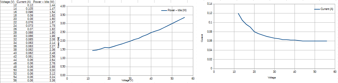
I have made the consumption measurements (one sample), without attachments - no cables, device basically idling... Let's say that bewteen 12 and 24 V, the device has more or less constant consumption. Above 24 V the increase of voltage results in increase of consumption.....transforming into heat. At 56 V the consumption is more than double compared to 12 V.
 ....while the size and performance of the current hEX S is otherwise totally sufficient