Last thing I’ll ask just to make sure nothing is left out, for your iperf tests, how were your devices connected? Which ports were used on the CCRs, were they on the same VLAN, etc? Routing between the switch chips will be done in CPU. Routing between VLANs also has overhead. So, depending on your setup you might have had some inefficiencies.
Edit: again, you have earned my respect. The number of people that either come to the forum, bitch about something “sucking” and then just quit, OR have an issue, are provided with suggestions, and then just go silent with no feedback, is large. You did your homework and shared the results which have me geeking out pretty good right now. Good on you and thanks for doing so!
It’s very heavy config. There’s sfp->VLAN->bridge and it’s bridge with use-ip-firewall=yes and stateful firewall on bridge which disables fasttrack entirely. So yeah I knew it’s very heavy use case that’s why I’m even more surprised that they managed to pull it off.
Servers were connected using 2x10G LACP to two CRS317, interconnected by 4x10G LACP. Then one of those CRS317 has been connected to CCR2004 and another one to CCR1009. Both using single SFP+. So it was quite symmetrical test. As for CCR2004PC vs CCR2004-12S+ I used sfp-sfpplus1 port so I could literally copy 1:1 the same config (since both devices have sfp-sfpplus1 port) and I was physically connecting patchcord to one or another. I used -P 1 (single thread connection) in iperf because NFS/CIFS and basically all popular storage protocols use one TCP tunnel per client and I wanted to test single client - single server bottleneck scenario.
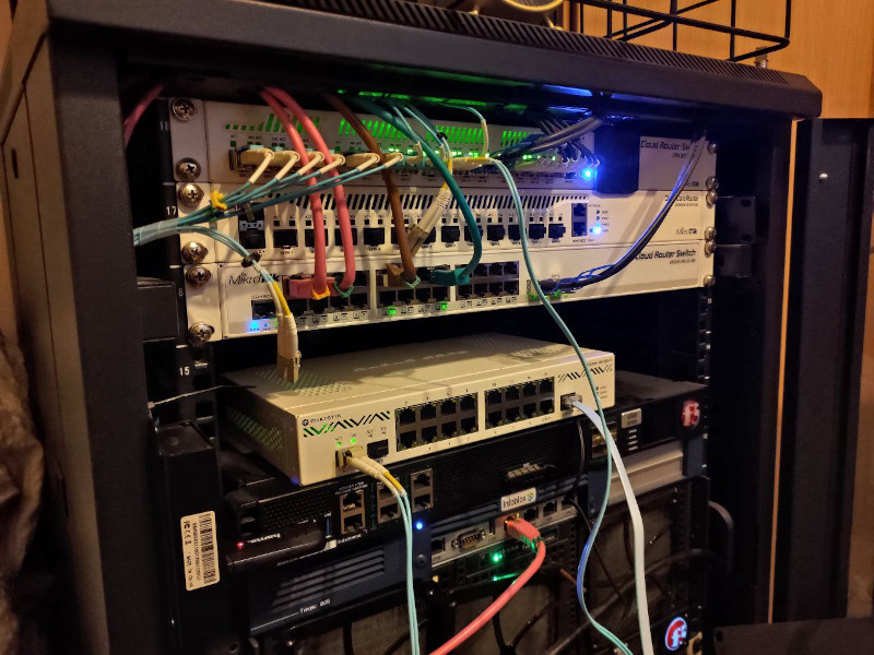
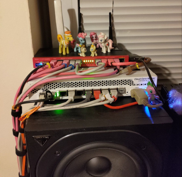
If you take alook at CCR1009 placement it’s quite clear why I needed CCR2004-PC form factor xD
As you can see I have LTE modem attached to CCR1009 so it’s kind of a problem… But maybe I’ll just move it to that RB2011 and hack it together somehow. Or maybe I’ll just move it to my ac² which is used as edge router to WAN. Since if I remember correctly the only reason why it’s connected to 1009 is because ARM architecture initially had issues with LTE modems support so it didn’t work with my ac² when I bought it.
Did you consider detrimental effects of vibrations to your networking gear?
I see you’ve got @vecernik87 visiting your RB2011 …
Probably because he only has gold-plated ethernet connector cables connected to ether1-4 but his 112kbps MP3 file server is connected to ether7 … and he wants to avoid jittery switch-chip ↔ switch-chip interconnect via CPU (and hopes for switch chip buffers to gracefully handle the 1Gbps → 100Mbps downgrade). What a nerd
I’m getting this question over and over and over again when someone sees that XD
Because two switches in RB2011 are separate and not connected - they’re bridged in software in default config. But there’s a lot of shenanigans in RouterOS with connection tracking when single connection gets looped by software bridge twice, eg: http://forum.mikrotik.com/t/loopback-nat-is-performed-only-once/121914/3
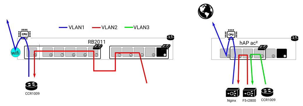
So I do not bridge them in software. I had more threads about similar issues with hairpin-like configs and conntrack. Basically mikrotik is keeping track of connection and it’s not treated as “state=new”, independent connection when it goes back to bridge to device for the second time so NAT and other stuff is not properly applied on second run through device. And since I have L2 transparent proxy, SSL decryption, IPS/IDS and some other devices in chain I do loop traffic more than once through routers (simply because I’m using switches in them as… well just physical switches - like in this case of RB2011). So all in all I’m using /ethernet switch config and CPU is isolated from traffic that passes through those switches on /interface switch vlan level. As a result RB2011 doesn’t (in software) see connections passing through those switches in “dumb port extender mode” when they simply go through there to reach CCR1009 and then it only sees those connections on CPU port when they go back to it (routed back by CCR1009) and properly applies NAT, firewall and stuff like this. So I’m essentially using RB2011 as two entirely separate devices - [simple switch] for CCR1009 just to have more physical ports in CCR in this place and [router+AP]. Okay maybe it’s a bit difficult to explain without picture so it’s case like this (arrow represents path of connection):
If I used software bridge then RB2011 would not properly apply NAT/mangle/fw rules to connection when it reaches it as blue path (since it’d already consider it established connection). I did my best to explain how it works XD. So in my config CPU port of switch chip has only like one VLAN allowed (blue) so CPU doesn’t see any connection when it goes there initially (red) and only sees it in software for the first time when it comes as blue. So since entire goal is to avoid RB2011 registering connections passing through those switches in connection tracking - I can’t bridge those two switches in software. THE END. xD
I have similar config on ac² where switch is isolated from CPU and connection tracking doesn’t see connections going through ether2-ether4 (just ac² has only one switch chip and doesn’t need such retarded physical interconnect like RB2011). So I’m basically using RB2011 as 2 completely unrelated devices and ac² as two completely unrelated devices. I could just buy two physical switches instead of using one device for 17 separate things and then try to workaround weird quirks for hours but according to simple math two routers are cheaper than two routers AND two switches xD
Does it still work like this? I don’t know. It did back in 2016. I configured it to work and never looked back.
Eh, that RB2011 works fine there since like 2012 or something (it was my very first mikrotik that I bought in high school to learn “real” networking) so I guess it’s not too bad XD
Nah man, gold plated ethernet is sooooo yesterday. Cool kids nowadays use gold plated optical patchcords. Because that… totally works like this. Photons get accelerated by proximity of gold plating. Or something like that. Yeah…
I tried to find gold plated, diamond encrusted LC-LC patchcords for CCR but couldn’t find anything dammit XD
Jokes aside I love looking at those absolutely ridiculous audiophile gear. It’s impressive in its own way that someone created something like this. I remember seeing power supply PCB with copper traces machined on CNC. They had thickness that would allow you to jumpstart 18 wheeler lmao XD Just when you thought you’ve seen everything in your life, they come up with something even more out of mind