A bridge has two roles - its is both like a switch connecting various ethernet ports together, and also like an ethernet port to pass traffic to services on the Mikrotik itself. Somewhat confusingly the settings for both of these roles are made under /interface bridge - the frame-types, ingress-filtering and pvid for the bridge port role are made here, whereas for all other ports attached to the bridge these are set under /interface bridge port
All your requirements are bogusly stated as configuration items (and thus you put yourself in a box).
Instead state your requirements in terms of use cases… what it is you would like your users to be able or not to be able to do.
Draw a network diagram showing the basic connectivity planned. Then one can start to figure out an optimal hardware design and software configuration.
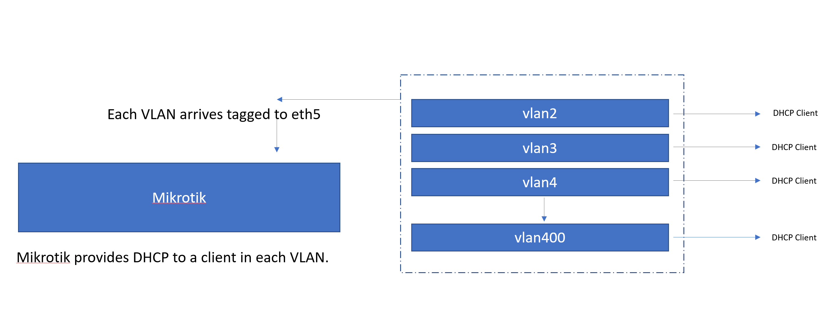
Thanks for your assistance. Hopefully the diagram below explains better. I am basically trying to terminate customer VLANS into one bridge that can assign IP addresses.
The bridge is completely missing in your drawing, but I guess I’ve got the point. Like any other port of the virtual switch called “bridge”, its virtual port named “bridge” can have a single “native” VLAN configured - in another words, it may act as an access port to a single VLAN, except that the pvid for this port named “bridge” is specified at the /interface bridge row whereas the pvid for all the other ports is specified using /interface bridge port rows. Access to all the other VLANs is only possible via the /interface vlan. In this regard, the vlan-filtering only allows to specify the native VLAN for each port of the bridge, but not to e.g. specify a VLAN ID for IP address, DHCP server etc. - the /interface vlan must be added as a separate object, and the IP address/subnet and DHCP server must be attached to that /interface vlan.
If your diagram is complete, i.e. you don’t need the Mikrotik to perform L2 forwarding between interfaces, you don’t need the bridge at all, and you can attach the /interface vlan rows directly to ether5.
I have this working already by using the /interface vlan method. I thought this was now defunct, and we were supposed to do everything within the bridge, so was trying to replicate the setup. The other reason is that the DHCP Option 82, only gives the VLAN number when its done without using /interface VLAN
Obviously on the router you have to define each vlan
-vlan’s interface is the bridge.
-IP pool for each vlan
-dchp-server for each vlan (interface is the vlan)
-IP address for each vlan
-dhcp-server-network for each vlan
Thanks for your help. But what I am trying to do is only have 1 DHCP server and 1 IP for all VLANs. Basically I want to treat the VLANs as a cable into a switch.
This will work if no device is accessible via two different VLANs - if it is, the bridge will get confused as frames from the same MAC address will be arriving via more than one bridge port. But there is no way to engage vlan-filtering in this scenario.
Thanks, I have it working in this way already. Does this mean all traffic would go through the CPU rather than using the hardware offloading then?
The scenario is a wholesale provider who hands over individual customers on a separate VLAN. I need to get each a public IP address, and I do not want to use PPPoE. If anyone has a better way of doing this without using a public IP at each end of every VLAN I would be really interested to hear.
Yes. But if I get your use case right, most of the traffic will be routed anyway, so even if the tagging and untagging was done in hardware, the limiting factor would be the router’s CPU throughput. And on a router, the task of tagging/untagging a frame and handling it on a bridge will not multiply the total amount of CPU spent per packet. CRS3xx with hardware routing in ROS 7 is a different story, there the impact would be larger, but for an ISP deployment, the capacity of L3 Hardware Offloading available on CRS3xx is insufficient anyway (if I get the information right, it can handle just hundreds of connections).
The CRS1xx/2xx can do the inverse task of choosing a VLAN ID for an ingress frame depending on its source MAC address, but I know no hardware which would add a tag on egress depending on the destination MAC address, plus would auto-learn the MAC addresses. So unless you can design your own ASIC, you’ll have to use a CPU powerful enough to do this in software.
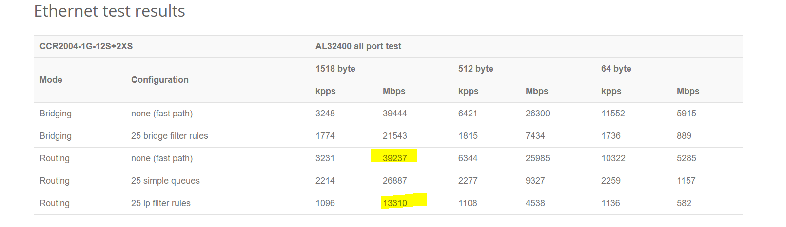
Am I reading it correct that for the above proposed setup I could expect approx. 40gbps throughput to onward transit for IPV4 traffic if using fastpath? Question - would the above setup allow fast path?
And for IPV6 this would drop to approx 13 - 26 gbps?
First of all, you cannot expect all the traffic to consist of large packets. Even for file downloads or web page downloads, i.e. connections that transport large payloads mostly in one direction using TCP, at least every fourth packet carrying a payload gets acknowledged by a small packet in the opposite direction, plus there is plenty of other traffic consisting of small packets (DNS queries, NTP synchronisation, VoIP, …). So the bits per second throughput stated for the 512-byte packets gives a better idea about real life throughput.
And I don’t understand at all where you’ve sourced the IPv6 figure from?