I’m pretty new to mikrotik routers. I have a RB3011 and need to setup following network structure:
192.168.88.1/22
On port 1 I have the uplink
On port 2-4 I want all IP’s from 192.168.88.1 - 192.168.88.254 with a dhcp server for the range of 192.168.88.60-192.168.88.200
On port 5&6 I want all IP’s from 192.168.89.1 - 192.168.89.254 with a dhcp server for the range of 192.168.89.60-192.168.89.200
On port 7&8 I want all IP’s from 192.168.90.1 - 192.168.90.254 with a dhcp server for the range of 192.168.90.60-192.168.90.200
On port 9&10 I want all IP’s from 192.168.91.1 - 192.168.91.254 with a dhcp server for the range of 192.168.91.60-192.168.91.200
All should have access to the internet via the uplink.
I have inserted the four dhcp pools under “IP Pool”, but I struggle what I have to enter in the “address list” besides the 192.168.88.1/22 in network 192.168.88.0 and with which interface. Do I have to put under “Bridge” the ports in different bridges? What is the exact config of the “DHCP Server” (currently only defconf under bridge with the dhcppool of 192.168.88.60-192.168.88.200 is there). Anything I have to enter under “Interface List”?
I’m totally lost and tried so many configurations typically crashed the mikrotik due to conflicts.
Thanks for help!
Step two - create four of everything
four bridges
assign ether ports to bridges as applicable
four LAN pools
four IP addresses
Four DHCP Servers
Assuming one WAN, keep the default masquerade rule under IP NAT.
Assuming one WAN, keep the default route rule in place and ensure that in DHCP Servers, use default route is selected (I believe it is automatically for the default lan created 192.168.88.0 etc but make sure it is for the other LANS (hint use copy feature in winbox).
Under interface list, there should be a WAN and a LAN already visible (default for ISP and single LAN)
For example if you had two ISPs and for the lans…
Doing the setup this way means all four networks are blocked from each other at layer2. They will not be able to see each other.
However, to prevent the router from connecting them at layer 3, you will need BLOCKING FW rules ( Forward Chain ).
You have a whole hockey sock of potential FW rules to block these LANS from seeing each other and not sure what is best to simplify?
Perhaps
forward chain,
source address list=Bridge_one (defined in IP address list at 192.168.88.1-192.168.88.254)
dst address list=**!**Bridge_one
action=DROP
Just a guess though, but this way you would only need four rules.
The exclamation mark “!” means everything but…
Two issues I see with my thinking and where real experts are needed:
The rule may have a side consequence of blocking LAN to INTERNET traffic ??
The default filter rules may allow LAN to LAN connection before it hits the drop rule???
First decide what the RB3011 will be used for, i.e. if only to route between subnets, then creating additional bridges should not be a performance issue. If you will be doing some switching, i.e. between ports 2,3 and 4, or between ports 5 and 6, etc. then creating multiple bridges might have a performance impact as you will lose hardware offloading on some of these bridges.
Once you decided on this, then there is another decision to make, do you want to go new “bridge” config “ROS 6.42.1” or “Master / Slave Port” config “ROS 6.40.8” once that has been decided on, from there my suggestion will be to create VLAN’s to separate these ports / subnets and configure with switch chip and or bridge to keep wire-speed
Hi CZFAN,
Quick question and I only want to discuss latest firmware, less confusion for me…
If he wants all subnets to see each other, why not just put all LANS on same bridge?
Would that retain wire speed?
How would using VLANs and bridges retain wire speed then?
I suppose you can put all subnets on same lane / bridge, but evey device will then get the layer 2 broadcasts, you will lose some security, etc which is not optimal and defeats the purpose of separating your network into multiple subnets / broadcast domains.
With the rb3011 and new ROS, 6.41 > you can create the VLAN’s on a single bridge, enable hardware offload, configure the VLAN’s in switch and retain wire speed
Thanks a lot for the feedback! I tried a little bit in the meantime but still the mikrotik gets confused. Main issue I have is that the four network areas must be fully visible to each other, because I will run some home automation servers from Loxone (4 in total, each one in one of the network which need to be able to talk to each other as in one subnet (they have following addresses: 192.168.88.10 (main), 192.168.89.10, 192.168.90.10 and 192.168.91.10). Regarding the later access control between the networks, I will setup then the firewall rules (I guess that will be some work…).
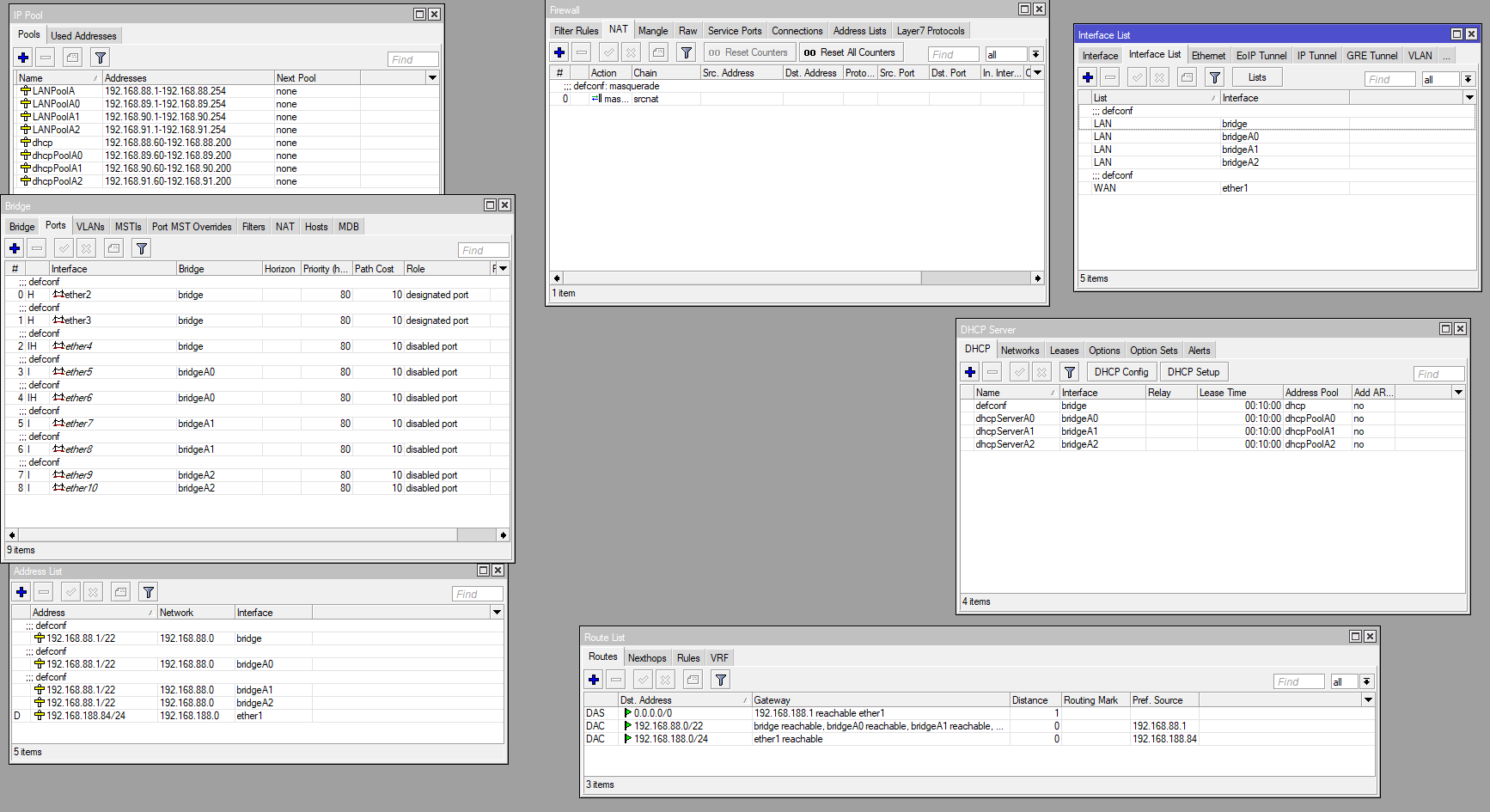
I have attached my current configuration as a picture. Not sure if the linking of the LAN to the different network bridges is correct and the dhcp server settings are right. At least with the current setting I get the right addresses when I connect, but the router is pretty instable and sometimes network connections fail and I can’t even reach the mikrotik anymore or the internet connection does not work.
By the way I will connect then in total 4 switches (ubiquiti unifi 16 port) each for one network area.
If you’re dividing your LAN to 4 subnets, you also need to assign RB3011 4 different LAN addresses (e.g. 192.168.88.1, 192.168.89.1, 192.168.90.1 and 192.168.91.1) to corresponding bridges. And use 24-bit subnet mask (e.g. 192.168.89.1/24, …). You can use same IP addresses for any other services you’re offering to your LAN devices (DNS server, …), but make sure FW rules allow needed connections.
If you configure devices in 192.168.89.x to use 24-bit subnet, they won’t be able to access default gateway 192.168.88.1. If you configure 192.168.89.x to use 22 bit address mask, then they will try to connect devices from e.g. 192.168.90.x directly but will fail as RB is standing on their way.
@thomasni, if you are going to add 4 x switches, i.e. one for each network, then it is very straight forward as the RB3011 will then only be a router between networks and internet.
All you have to do then is, remove bridges so each port becomes a routing port, add a IP address to relevant port for the gateway, attache the relevant DHCP to this port and then connect you switch to this.
Then you control who has access to which network via firewall filter rules
We are still in the stage of determining requirements before designs can be formulated.
What I have gleaned is that there are only four devices that need to speak with each other but why do they have to be on four different LANs ??
Are they serving devices within the same LAN, or is it a geographical/physical location game?
“home automation servers from Loxone”
Do these devices need to talk to other devices on the network besides the other servers, and by that I mean on the same LAN structure?
If so how are they connected to other devices?
a. by low voltage wire?
b. Ethernet?
c. wifi?
How do you access these servers for monitoring or updates etc…
a. from your PC?
b. from an iphone app? and if so
i. through the wifi in your home?
ii. through external cloud connection (wifi or cellular out to the internet)
Read the OP again, I will quote it for your reference:
“I have a RB3011 and need to setup following network structure:
192.168.88.1/22
On port 1 I have the uplink
On port 2-4 I want all IP’s from 192.168.88.1 - 192.168.88.254 with a dhcp server for the range of 192.168.88.60-192.168.88.200
On port 5&6 I want all IP’s from 192.168.89.1 - 192.168.89.254 with a dhcp server for the range of 192.168.89.60-192.168.89.200
On port 7&8 I want all IP’s from 192.168.90.1 - 192.168.90.254 with a dhcp server for the range of 192.168.90.60-192.168.90.200
On port 9&10 I want all IP’s from 192.168.91.1 - 192.168.91.254 with a dhcp server for the range of 192.168.91.60-192.168.91.200
All should have access to the internet via the uplink.”