If only you started with
instead of
it would be much easier to solve the problem
If only you started with
instead of
it would be much easier to solve the problem
Current situation:
Everything works, but... CPU at 93%.
I tried testing a few rules and I think it's the Routing Rules that are causing the CPU to be high...
Basically, I use mangle to manage forwarding traffic and routing rules to manage traffic from the router (output).
I can't do it with mangle. So in the end, I end up with double rules...
in particular for the routing rules, since I can't enter address lists in the conditions, I'm forced to put many rules in succession (I don't know if this affects the CPU)
/routing rule add action=lookup-only-in-table disabled=no src-address=10.10.64.125/32 table=rtab-WAN1
/routing rule add action=lookup-only-in-table disabled=no src-address=10.10.64.133/32 table=rtab-WAN2
/routing rule add action=lookup-only-in-table dst-address=10.10.96.40/29 table=main
/routing rule add action=lookup-only-in-table dst-address=10.10.96.48/29 table=main
/routing rule add action=lookup-only-in-table dst-address=10.10.96.64/28 table=main
/routing rule add action=lookup-only-in-table dst-address=10.10.96.56/29 table=main
/routing rule add action=lookup-only-in-table dst-address=10.10.97.0/24 table=main
/routing rule add action=lookup-only-in-table dst-address=10.10.98.0/24 table=main
/routing rule add action=lookup-only-in-table dst-address=10.10.110.0/23 table=main
/routing rule add action=lookup-only-in-table dst-address=10.10.108.0/23 table=main
/routing rule add action=lookup-only-in-table disabled=no dst-address=192.168.150.0/24 table=main
/routing rule add action=lookup-only-in-table dst-address=10.30.212.0/24 table=main
/routing rule add action=lookup-only-in-table dst-address=10.10.60.0/22 table=main
/routing rule add action=lookup-only-in-table disabled=no dst-address=0.0.0.0/0 table=rtab-WAN1
however
if I try to disable the mangle rules, the CPU is not affected...
if I disable the block of rules with the dst-addresses before the one at 0.0.0.0/0, the CPU drops from 93% to 30%.
EDIT:
No, well... the CPU usage only drops because disabling the routing rules in question means that data no longer passes through...
CPU usage depends precisely on the network logic... how could I optimize it?
Translated with DeepL.com (free version)
The problem is I have no concept of what your network even looks like, despite the diagram its only more confusing than helpful and as Bartoz points out the explanation is weak.
Identify all the user(s)/devices(s) including the admin
Identify all the their traffic they need to accomplish
WANS --> provide a clear presentation of which WANS the network has available through which device.
Are we talking one router with a multiwan connection to the internet?
or Multiple Routers terminating internet connections
or one router handling terminating all internet but the internet comes from other devices (acting as switches)
Which router is providing the VLAN subnets and thus effectively also the firewall rules.
Break down your diagram into digestible and understandable bits
I apologize if I am not making myself clear... but I don't know how else to explain the situation...
Let's start from the beginning... there are three routers connected to each other via Ethernet... each router is located on a different tower... but in the same place... a site, let's call it site A
I have connected different categories of devices to the ports of the three routers: there are several pairs of radio links that connect me to other sites, each of these pairs must be separated from the others and for this reason is included in a different VLAN
then I have WiFi devices, which must be in a separate VLAN, and IoT devices, meaning cameras, microphones, routers, mini PCs, etc., which will also have their own VLAN...
Let's start from this: several VLANs, all isolated from each other, managed by router A.
From router A, I also have to route to other networks that I have to address through the pairs of radio bridges.
The main purpose of this structure is not to connect to the internet... the purpose is to allow a device at site C (for example) or site F (for example) to reach a device at site A.
Let's start with this for now... then we'll clarify other details.
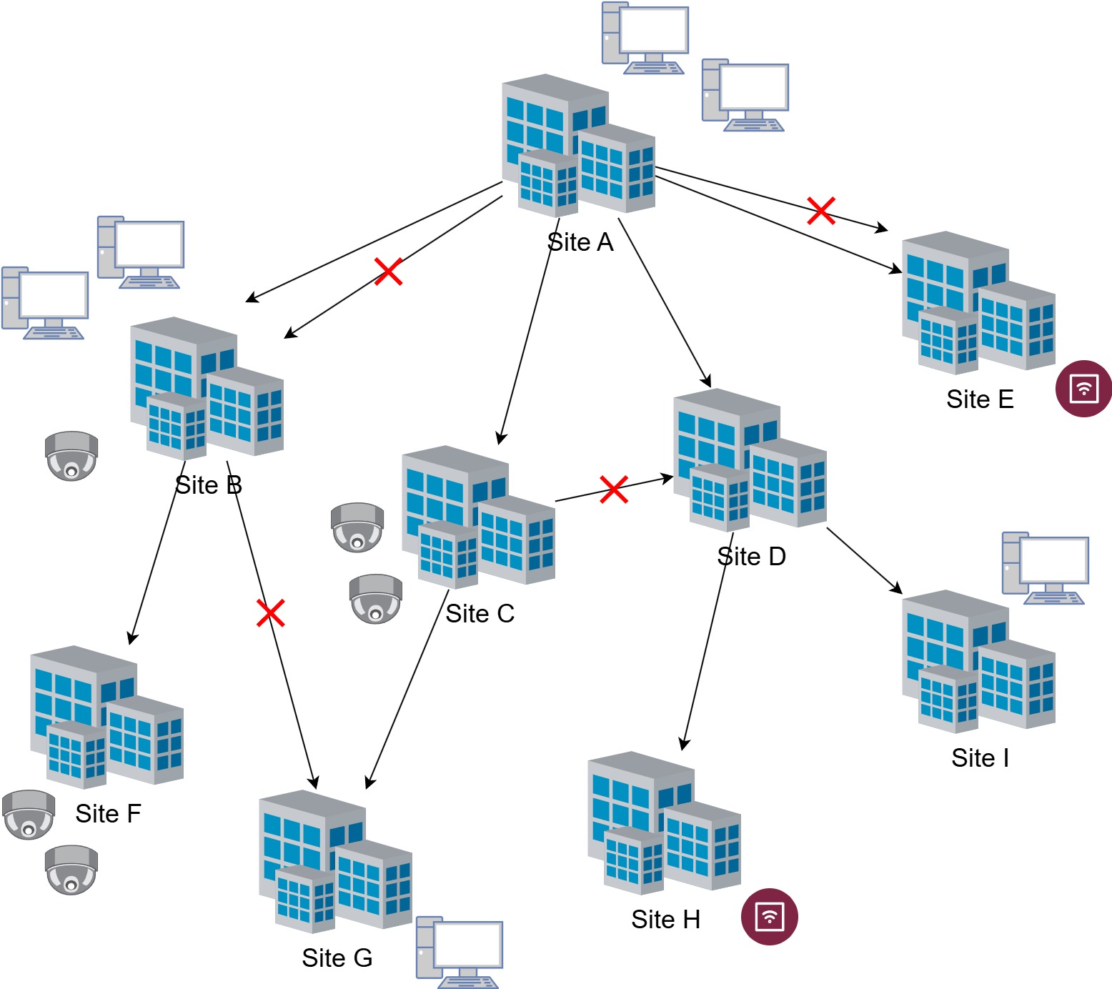
The structure of the sites is pyramid-shaped...
each line represents a connection made via a pair of radio links... there may also be two or more connections from site to site...
each site has PCs and various devices
I need to allow a PC at any site to connect to a specific device at another site...
and use the routers at the site to choose the route to take
When I talk about WAN, I mean the lines that carry the connection upwards
All sites consist of one or more routers with the same topology... all connected to each other and managed by the main router... even if, for example, the port with the radio link to the previous site is on one of the other routers.
Seems that you need to implement OSPF+iBGP routing
Currently, I do everything with static routes, disabling redundant ports...
If a radio link goes down, I close one port and open the other.
But I would like to be able to leave everything open and manage everything by routing traffic as I wish...
From the router above, I would like to be able to set the IP address on the router corresponding to the input VLAN as the gateway for the route to the device... and consequently obtain a response from the same VLAN...
Thanks, its more than my limited amount of knowledge can help with. Concur with Bartoz that there are functionalities within the MT routers best suited to deal with your scenario. Either someone is able to chime in with the knowledge or, if time pressed, its certainly one situation where its worth it for a one time consult with an expert and then you can manage it from there.......... https://mikrotik.com/consultants
With my latest configuration, I can do what I want...
I choose the route to take from the upper router and the device (actually, often groups of devices) responds on the same port...
The VLANs are separate from each other and only go to the upper router, except in some specific cases...
I can also set the route to take if the device needs to open a new connection to the upper router...
However, my management is not optimized... My CPU is at 90%... I should be able to simplify the mangle or routing rules.
/interface bridge add name=bridge pvid=99 vlan-filtering=yes

/interface ethernet set [ find default-name=ether1 ] loop-protect=on rx-flow-control=on tx-flow-control=on
/interface ethernet set [ find default-name=ether2 ] loop-protect=on poe-out=off rx-flow-control=on tx-flow-control=on
/interface ethernet set [ find default-name=ether3 ] comment="" loop-protect=on poe-out=off rx-flow-control=on tx-flow-control=on
/interface ethernet set [ find default-name=ether4 ] comment="TRUNK PORT" loop-protect=on poe-out=off rx-flow-control=on tx-flow-control=on
/interface ethernet set [ find default-name=ether5 ] comment="RADIO WAN2" loop-protect=on poe-out=forced-on poe-priority=5 rx-flow-control=on tx-flow-control=on
/interface ethernet set [ find default-name=sfp1 ] loop-protect=on rx-flow-control=on tx-flow-control=on

/interface vlan add comment="VLAN - WAN1" interface=bridge name=vlan101_WAN vlan-id=101
/interface vlan add comment="VLAN - WAN2" interface=bridge name=vlan102_WAN vlan-id=102
/interface vlan add comment="VLAN - LAN" interface=bridge name=vlan201_LAN vlan-id=201
/interface vlan add comment="VLAN - WIFI" interface=bridge name=vlan301_WIFI vlan-id=301
/interface vlan add comment="VLAN - PTP1" interface=bridge name=vlan501_PTP vlan-id=501
/interface vlan add comment="VLAN - PTP2" interface=bridge name=vlan502_PTP vlan-id=502
/interface vlan add comment="VLAN - PTP3" interface=bridge name=vlan503_PTP vlan-id=503
/interface vlan add comment="VLAN - PTP4" interface=bridge name=vlan504_PTP vlan-id=504

/interface list add name=WAN1_Ports
/interface list add name=WAN2_Ports
/interface list add name=LAN_Ports
/interface list add name=WIFI_Ports
/interface list add name=TAGGED_Ports
/interface list add name=PTP1_Ports
/interface list add name=PTP2_Ports
/interface list add name=PTP3_Ports
/interface list add name=PTP4_Ports

/routing table add disabled=no fib name=rtab-WAN1
/routing table add disabled=no fib name=rtab-WAN2


/interface bridge port add bridge=bridge frame-types=admit-only-vlan-tagged interface=TAGGED_Ports pvid=99
/interface bridge port add bridge=bridge frame-types=admit-only-untagged-and-priority-tagged interface=WAN1_Ports pvid=101
/interface bridge port add bridge=bridge frame-types=admit-only-untagged-and-priority-tagged interface=WAN2_Ports pvid=102
/interface bridge port add bridge=bridge frame-types=admit-only-untagged-and-priority-tagged interface=LAN_Ports pvid=201
/interface bridge port add bridge=bridge frame-types=admit-only-untagged-and-priority-tagged interface=WIFI_Ports pvid=301
/interface bridge port add bridge=bridge frame-types=admit-only-untagged-and-priority-tagged interface=PTP1_Ports pvid=501
/interface bridge port add bridge=bridge frame-types=admit-only-untagged-and-priority-tagged interface=PTP2_Ports pvid=502
/interface bridge port add bridge=bridge frame-types=admit-only-untagged-and-priority-tagged interface=PTP3_Ports pvid=503
/interface bridge port add bridge=bridge frame-types=admit-only-untagged-and-priority-tagged interface=PTP4_Ports pvid=504

/interface bridge vlan add bridge=bridge tagged=bridge,TAGGED_Ports vlan-ids=101
/interface bridge vlan add bridge=bridge tagged=bridge,TAGGED_Ports vlan-ids=102
/interface bridge vlan add bridge=bridge tagged=bridge,TAGGED_Ports vlan-ids=201
/interface bridge vlan add bridge=bridge tagged=bridge,TAGGED_Ports vlan-ids=301
/interface bridge vlan add bridge=bridge tagged=bridge,TAGGED_Ports vlan-ids=501
/interface bridge vlan add bridge=bridge tagged=bridge,TAGGED_Ports vlan-ids=502
/interface bridge vlan add bridge=bridge tagged=bridge,TAGGED_Ports vlan-ids=503
/interface bridge vlan add bridge=bridge tagged=bridge,TAGGED_Ports vlan-ids=504

/interface list member add interface=ether3 list=LAN_Ports
/interface list member add interface=ether4 list=TAGGED_Ports
/interface list member add interface=ether5 list=WAN2_Ports

/ip address add address=10.10.64.125/29 interface=vlan101_WAN network=10.10.64.120
/ip address add address=10.10.64.133/29 interface=vlan102_WAN network=10.10.64.128
/ip address add address=10.10.97.250/24 interface=vlan201_LAN network=10.10.97.0
/ip address add address=10.10.98.250/24 interface=vlan201_LAN network=10.10.98.0
/ip address add address=10.10.99.250/24 interface=vlan301_WIFI network=10.10.99.0
/ip address add address=10.10.96.46/29 interface=vlan501_PTP network=10.10.96.40
/ip address add address=10.10.96.54/29 interface=vlan502_PTP network=10.10.96.48
/ip address add address=10.10.96.78/28 interface=vlan504_PTP network=10.10.96.64
/ip address add address=10.10.96.62/29 interface=vlan503_PTP network=10.10.96.56

/ip dns set allow-remote-requests=yes servers=10.10.64.126
/ip firewall address-list add address=google.com list=test_dns
/ip firewall address-list add address=10.10.97.0/24 list=LAN_Networks
/ip firewall address-list add address=10.10.98.0/24 list=LAN_Networks
/ip firewall address-list add address=10.10.96.40/29 list=PTP1_Networks
/ip firewall address-list add address=10.10.110.0/23 list=PTP1_Networks
/ip firewall address-list add address=10.10.96.48/29 list=PTP2_Networks
/ip firewall address-list add address=10.10.60.0/22 list=PTP2_Networks
/ip firewall address-list add address=10.30.212.0/24 list=PTP2_Networks
/ip firewall address-list add address=10.10.96.56/29 list=PTP3_Networks
/ip firewall address-list add address=10.10.108.0/23 list=PTP3_Networks
/ip firewall address-list add address=10.10.96.64/28 list=PTP4_Networks
/ip firewall address-list add address=10.10.97.0/24 list=LOCAL_IPs
/ip firewall address-list add address=10.10.98.0/24 list=LOCAL_IPs
/ip firewall address-list add address=10.10.96.40/29 list=LOCAL_IPs
/ip firewall address-list add address=10.10.96.48/29 list=LOCAL_IPs
/ip firewall address-list add address=10.10.96.64/28 list=LOCAL_IPs
/ip firewall address-list add address=10.10.96.56/29 list=LOCAL_IPs
/ip firewall address-list add address=10.10.110.0/23 list=LOCAL_IPs
/ip firewall address-list add address=10.10.108.0/23 list=LOCAL_IPs
/ip firewall address-list add address=10.30.212.0/24 list=LOCAL_IPs
/ip firewall address-list add address=10.10.60.0/22 list=LOCAL_IPs

/ip firewall filter add action=accept chain=input comment="defconf: accept established,related,untracked" connection-state=established,related,untracked
/ip firewall filter add action=drop chain=input comment="defconf: drop invalid" connection-state=invalid
/ip firewall filter add action=accept chain=forward comment="defconf: accept established,related, untracked" connection-state=established,related,untracked
/ip firewall filter add action=drop chain=forward comment="defconf: drop invalid" connection-state=invalid
/ip firewall filter add action=accept chain=forward comment="accept forward with mark ( from_WAN\? / to_WAN\? )" connection-mark=!no-mark
/ip firewall filter add action=drop chain=forward comment="drop forward"

/ip firewall mangle add action=mark-connection chain=prerouting comment="MARK NEW CONNECTION FROM WAN1" connection-mark=no-mark connection-state=new in-interface=vlan101_WAN new-connection-mark=from_WAN1
/ip firewall mangle add action=mark-connection chain=prerouting comment="MARK NEW CONNECTION FROM WAN2" connection-mark=no-mark connection-state=new in-interface=vlan102_WAN new-connection-mark=from_WAN2
/ip firewall mangle add action=mark-connection chain=prerouting comment="MARK NEW CONNECTION FROM LAN OR PTPs NETWORK TO WAN WITH DEFAULT WAN (WAN1)" connection-mark=no-mark connection-state=new dst-address-list=!LOCAL_IPs new-connection-mark=to_WAN1 src-address-list=LOCAL_IPs
/ip firewall mangle add action=mark-routing chain=prerouting comment="ALL CONNECTION MARKED FROM WAN1 REPLY TO WAN1" connection-mark=from_WAN1 in-interface=!vlan101_WAN new-routing-mark=rtab-WAN1 passthrough=no
/ip firewall mangle add action=mark-routing chain=prerouting comment="ALL CONNECTION MARKED FROM WAN2 REPLY TO WAN2" connection-mark=from_WAN2 in-interface=!vlan102_WAN new-routing-mark=rtab-WAN2 passthrough=no
/ip firewall mangle add action=mark-routing chain=prerouting comment="ALL CONNECTION MARKED WITH TO-WAN1 GO TO RTAB-WAN1 TABLE" connection-mark=to_WAN1 dst-address-list=!LOCAL_IPs new-routing-mark=rtab-WAN1 passthrough=no src-address-list=LOCAL_IPs
/ip firewall mangle add action=mark-routing chain=prerouting comment="ALL CONNECTION MARKED WITH TO-WAN2 GO TO RTAB-WAN2 TABLE" connection-mark=to_WAN2 dst-address-list=!LOCAL_IPs new-routing-mark=rtab-WAN2 passthrough=no src-address-list=LOCAL_IPs

/ip route add disabled=no distance=1 dst-address=10.10.110.0/23 gateway=10.10.96.45 routing-table=main scope=30 suppress-hw-offload=no target-scope=10
/ip route add disabled=no distance=1 dst-address=10.10.108.0/23 gateway=10.10.96.61 routing-table=main scope=30 suppress-hw-offload=no target-scope=10
/ip route add disabled=no distance=1 dst-address=10.10.60.0/22 gateway=10.10.96.53 routing-table=main scope=30 suppress-hw-offload=no target-scope=10
/ip route add disabled=no distance=1 dst-address=10.30.212.0/24 gateway=10.10.96.53 routing-table=main scope=30 suppress-hw-offload=no target-scope=10
/ip route add disabled=no distance=5 dst-address=0.0.0.0/0 gateway=10.10.64.126@main routing-table=rtab-WAN1 scope=30 suppress-hw-offload=no target-scope=10
/ip route add disabled=no distance=5 dst-address=0.0.0.0/0 gateway=10.10.64.134@main routing-table=rtab-WAN2 scope=30 suppress-hw-offload=no target-scope=10

/routing rule add action=lookup-only-in-table disabled=no src-address=10.10.64.125/32 table=rtab-WAN1
/routing rule add action=lookup-only-in-table disabled=no src-address=10.10.64.133/32 table=rtab-WAN2
/routing rule add action=lookup-only-in-table disabled=yes dst-address=0.0.0.0/0 table=rtab-WAN1

/system ntp client set enabled=yes
/system ntp server set broadcast=yes enabled=yes multicast=yes
/system ntp client servers add address=10.10.64.126
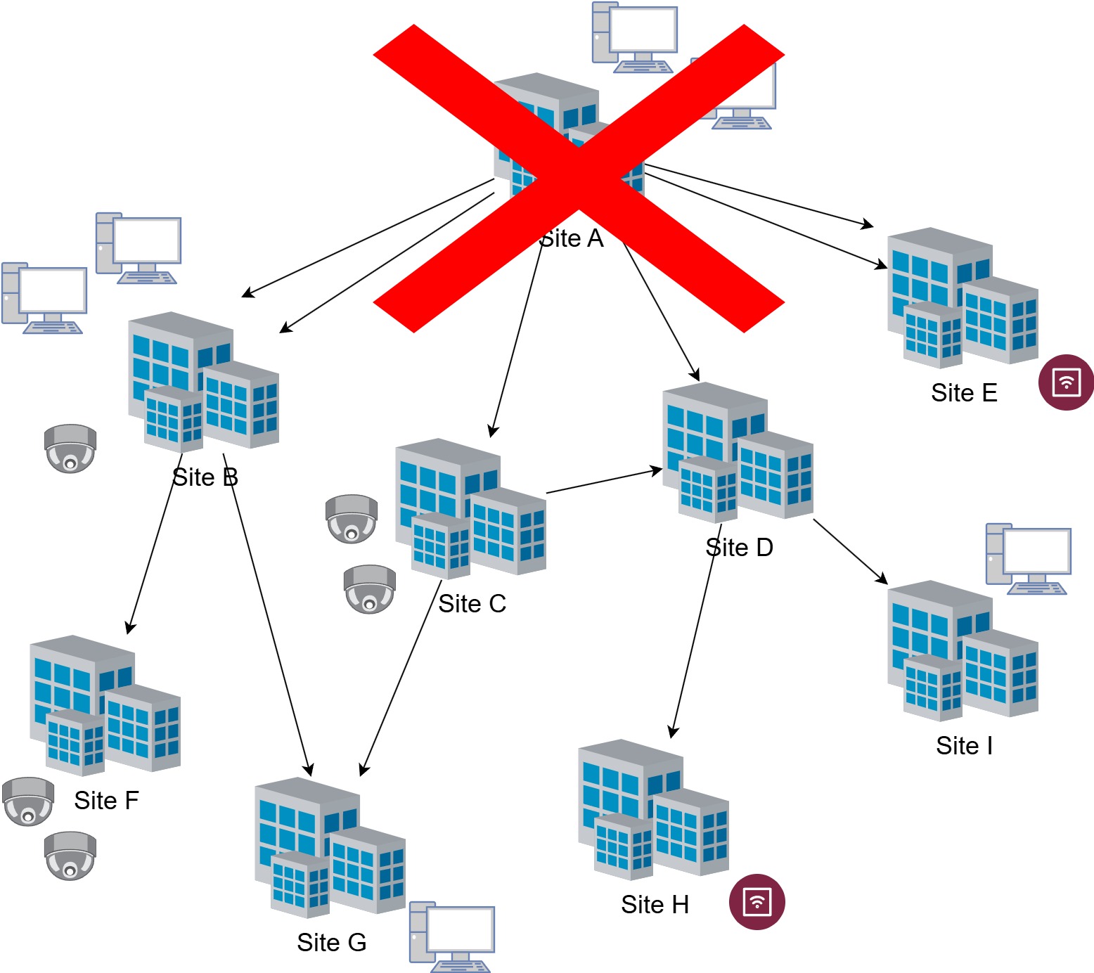
One router dies, all network dies. Just 2cents.
What happens when you switch off the router @ Site A?
Currently, if site A goes down, the routes on site B would still allow me to reach some devices from some PCs... For maintenance purposes, I would access site B (via 5g recovery), disable the port to site A, and enable the port to site G, thus also reaching site C... then I would enable the port to D... obviously, I have to close all the ports to A to avoid loops as soon as site A comes back online
basically, I can more or less get everything back up and running...
It's like having a car equipped with modern Cranktronic air conditioning ![]()
I do everything manually because, with continuous video recording, automation caused latency and drops in video streams...
Furthermore, the use of radio links as a site-to-site connection does not provide the same bandwidth continuity as an Ethernet or fiber cable, and this affects all protocols that “calculate” the best route.
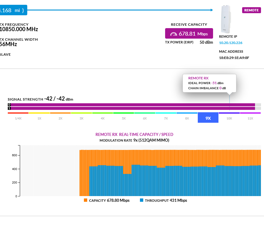
At present, everything is working smoothly, and this is the effective throughput of the most used “channel.”
In any case, I am writing on this forum precisely to seek new solutions and advice... What would you do? consider that I am working on a network that is already set up this way... I cannot throw everything away, but I should make changes gradually as I go along.
Simply RSTP do it's job with 2 concurrent links. You chose the main, no automatism.
Just when the link go down, the other is instantly used, etc.
Just a minor remark from my side reading this ...
Are you Superman ?
You can make changes manually faster then any routing protocol which was designed for this ?
And when you do it manually, there is no disconnect for video streams etc ?
A suggestion was already made a couple of posts up, I believe.
I see a second one now also pops up.
It's not a question of being faster than the router... it's not a question of speed but of stability...
For the video streams I manage, it's better to skip the signal completely than to have them remain active but constantly disconnecting and reconnecting, or losing fps and becoming fragmented...
Even the RSTP protocol becomes a problem if it constantly changes the active port due to the instability of the WiFi signal from the radio bridges... All these things have been tested over time, which is why we chose to make changes manually... that is, based on our needs...
and in any case, with the RSTP protocol, I could only do failover... I might also need to balance the flows...
I don't know if you have experience with radio bridge transmission... and we're not talking about radio bridges for ISP purposes, but for point-to-point networks.
But I can guarantee that they complicate things for the protocols used by routers because, at the end, the Ethernet port to which they are connected is certainly rated at 1Gbit, but then the available bandwidth can change drastically, even depending on the weather...
For example, the first time I tried balancing, I created a bond between the two interfaces with the radio links... but the throughput was terrible...
Then again, maybe I'm just not very good at it, maybe I can't configure the protocols properly...
On on the contrary, I have no experience with iBGP and OSPF, I should study them a little.
I think you will hardly find one on this forum .... sarcasm.