I’m sure the differences are there (SFP, USB ports, for example), but I’m trying to find the differences that would make a difference to me (I know, you can’t read my mind or know my needs).
Are they both reliable? Well-performing? Plays well with 7.1x?
I’m resorting to talking to myself (not the first time).
Both devices use the same chipset
The Netbox 5ax is 5ghz only, required an external antenna, and has passive POE.
The Netmetal ax is 2.4 & 5ghz, requires an extenal antenna, and has passive POE.
The wAPax (another outdoor AP) has 2.4 & 5ghz, with build-in antenna, and active POE, but is not omnidirectional. Quite a big difference in gain betwen front and sides/back.
I don’t mind (actually, I like) the requirement for an external antenna as I’m a big believer in the importance of antenna design and location.
To me, for a generalized outdoor AP, with omni coverage, the Netbox 5ax and the wAP do not meet the needs – 2.4 is important for IoT and distance/penetration, and omni is not provided by the wAP.
That leaves (naturally) the most expensive of the three: Netmetal ax.
I’ve read past threads on this and I see that there is disagreement.
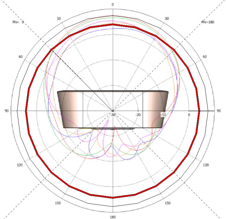
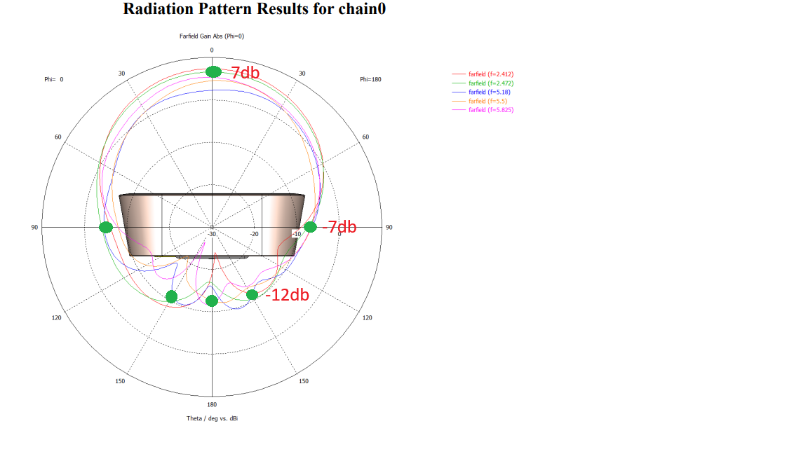
I’m not an expert at antenna radiation plotting, but this sure looks to me to be what I would call highly directional with ~7db gain in front and 7db loss to the sides and 10db loss to the rear in the azimuth-axis.
I haven’t heard a clear conclusion, but from various past posts, something else to note is that one or both of the the net* devices may have radios locked to “location=outdoor”, which affects what frequencies and at what powers can be selected. The wAP is not “exclusively outdoor use”, so much better chance that one has “location=indoor” frequencies unlocked.
Otherwise, the main SoC (incl. the 2.4 GHz radio which remains not-wired on the netbox) and the 5GHz radio of all three are exactly the same, so things like system stability or specific radio driver quirks should be basically identical as well.
Looking at the specs and shapes, it honestly feels that at least here on the 5ax generation, the netmetal vs the netbox is kind of like back-in-the-day you’d have a “Device” and “Device Lite” budget variant.
Thanks for confirming the lack of a conclusion on whether the wAP is directional.
I don’t know if the radios are locked to “outdoors,” nor what exactly that would be mean for frequency and tx power.
The “Device Lite” comparison might very well be apt, but the details of what MT means by “lite” in this particular case are what is important – and yet not clear.
I still see nothing that would lead me to get a Netbox 5ax with only the single band.
And, between the wAPax and the Netmetal ax, I still don’t see any single factor being nearly as significant as the directionality.
The w stands for wall.
The conclusions were already made.
The antenna pattern of the wap Ax is toward the front of the device.
It is debatable whether is 90° or more like 120*.
Not really. By definition (see wikipedia article width/height of antenna beam is defined by width/height of main lobe, which is the angle at which radiated power drops to half of maximum (i.e. 3dB lower than max).
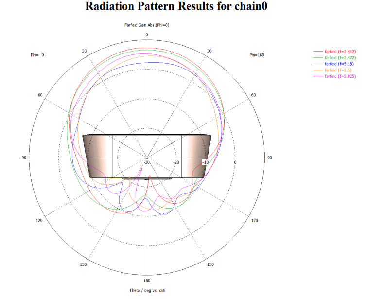
And judging from the radiation pattern image, posted by @Josephny, that happens at around 30°-45° from the center. Hence wAP ax has beam width somewhere in range 60°-90° (and surely not 120°). Sure this doesn’t mean that outside main lobe there isn’t usable signal. For example, MNOs often use antennas with nominal beam width of 65° … and place them at 120° azimuth separation (i.e. using 3 to cover whole space around cell tower) … performance in directions outside main beams will be degraded for sure (mainly at longer distances), but it’ll be degraded more due to interference from the co-located adjacent cell. The later is not the case with WiFi where APs should be using non-overlaping channels (and that’s a must for colocated APs).
I would say that while interference from 120* extremely close neighbor antennas is typically not the problem, the problem is signal degradation between 90 and 270* on a wAP is substantial (with most of the degradation between 120 and 240*). The difference between +7db and -7db (0* to 120*) is tremendous outdoors (where distance between AP and station tends to be greater than it is indoors).
It can be depending on geometry. Devices don’t like “being shouted at” and two close APs operating on same frequency will be shouting at each other. APs, operating on diffetent frequencies, won’t directly shout at each other, but will degrade each other’s Rx sensitivity due to effect on AGC of Rx pre-amplifier (which is wide-band and there are no actual RF band pass filters set on operating frequency of each AP, so AGC will adjust to strongest signal received inside whole WiFi band, even if it’s irelevant for digital Rx stages).
Yup, no doubt that wAP ax is s device with directional antenna and its beam width is between 60° and 90° … with reduced coverage elsewhere.
Oh yes, I didn’t mean that close range tx is not a problem. I just meant that in a typical home environment, there aren’t transmitters within close proximity of each other as there are on towers with sector devices dividing 360 into 3, 120* areas all within a foot of each other.
Yup, no doubt that wAP ax is s device with directional antenna and its beam width is between 60° and 90° … with reduced coverage elsewhere.
[/quote]
Would be nice for MT to make that a little clearer. The “w” for wall is not clear, and even if it was, it would still require a couple of brain cells to figure out that a wall mounted AP would certainly be better designed to have an antenna with gain in the direction away from the wall.
Interestingly, the Netmetal (and the Netbox) both prominantly identify the option to use external omni antennas (as they should). Seems like the tiny little logical jump to prominantly advertise (position) each of these devices with clarity as to directionality is missing.
It still (IMHO) remains debatable.
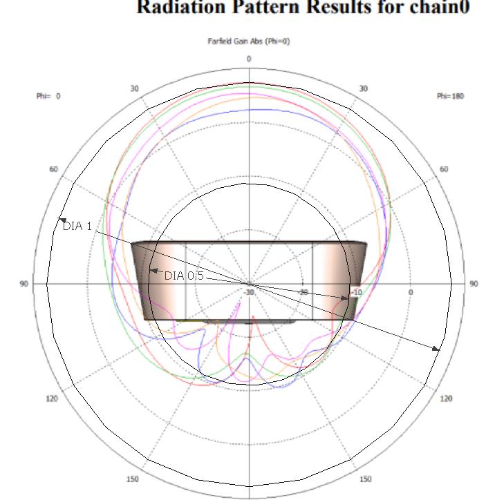
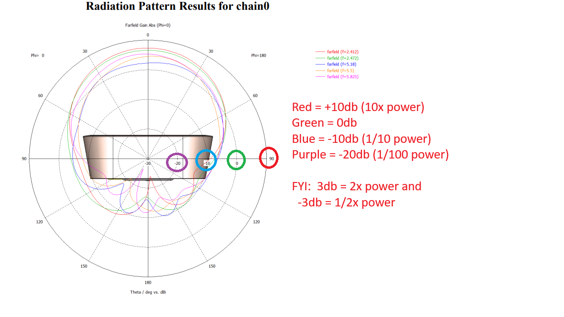
Try applying the 0.5 circle on that pattern image, and you will see that (according to the half power definition) it is apparently an omnidirectional (which it isn’t).
All the images I have seen are about much more directional antennas, with a rather narrow lobe, so maybe it simply doesn’t properly apply to this particular shape.
I don’t understand what you mean by “applying the 0.5 circle” but this is how I read it (and I hope someone will correct me if I’m wrong).
0* azimuth is about 7db gain.
90* is about -7db loss.
180* is about -12db loss.
The difference between 7db gain and 7db loss (14db) is about 25x the power. That is, 1 watt into a 7db gain antenna would produce an effective radiated power of 5 watts. The same 1 watt into a -7db antenna would produce an effective output of 0.2 watts. That is a factor of 25.
And, of course, the effective radiated power is, well, what is effective.
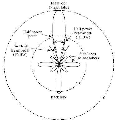
The definition talks about “main lobe” … and each antenna has exactly one main lobe, on your diagram the one pointing directly upwards.
If you want to nitpick with the diagram … that would be “bi-directional” antenna … although true bidirectional antennas have similar antenna gain in both directions, your has (say) -2.5dBi in the backward direction.
All the images I have seen are about much more directional antennas, with a rather narrow lobe, so maybe it simply doesn’t properly apply to this particular shape.
What doesn’t apply? Take maximum power (in wAP ax diagram that’s upward direction), draw a circle with 3dBi less power and see where it intersects power diagram. I’m not drawing the circle, but it is somewhere between ±30° and ±45°.
The circle you’ve drawn is the maximum value … make circle of 3dBi smaller radius and you’ll see what I’m talking about.
The circle with 3db smaller radius is a circle with half the radius, which is what I have drawn (there are two circles drawn over the image, one with Dia 1 and one with Dia 0.5).
The result is apparently meaningless with that shape.
No, you drew circle with maximum gain (+7dBi) and circle with approx -12dBi (so 19dB difference in power which is factor of around 80 if measured in Watts … instead of factor of 2). What you should have drawn is circle at maximum gain (+7dBi) and circle with 3dBi less than maximum … which is at +4dBi. And that’s the half of power.
Power calculus:
By definition, dBm means 1 deci Bell (referenced at 1mW). So 0dBm is 1mW. And “deci” means that calculation includes factor of 10 on the logarithmic side.
Or in equation:
P[dBm] = 10*log10(P[mW]/1mW)
And then a simple table:
0dBm = 1mW
0dBm + 3dB = 3dBm = 2mW (adding 3dB to logarithmic value means factor of 1.995 in linear value, which we usually round to 2)
7 dBm = 5mW
10 dBm = 10mW
13dBm = 20mW
30 dBm = 1W
5 mW / 2 = 2.5 mW = 4dBm ( = 7 dBm - 3 dBm)
And definition of beam width is talking about half power in liner values, so in Watts. Half power then means 3dB less than maximum power.
 :
:

 (maybe even a little less)