but I’m able to ping 8.8.8.8 even if I unplug the 10.0.2.1 interface, its passes through the alternative route and netwatch can’t see that it got disabled
When you ping a public IP address it will route it if you have set up failover… that is the aim of failover!
If you do netwatch in failover mode to check if “something is unplugged” then ping local IP address of the box (like upstream router).
If you ping a public address it will find it (you have a generic distance 2 route via 192.168…).
The whole config is messed up and thus getting to a properly setup failover is going to be difficult.
Lets clean up what we can and then troubleshooting one area will be much easier.
(1) The first thing to point out is that your bridge setup is erroneous.
a. the vlans interface should be the BRIDGE not ether2
b. you define six vlans and then provide only 4 pools, 4 server networks, and 3 dhcps server etc AKA → your vlan setups are incomplete!!
c. I see only four addresses for six vlans, and only one WAN address and was expecting a second backup WAN address?
d. I see two admin networks, do you really need two, and a third one, .102. which is not defined anywhere??? (OKAY I see its for vpn access??)
(2) Keep the mac Winbox-mac server for winbox access but
this one should be set to none as its a security risk.
/tool mac-server
set allowed-interface-list=MANAGEMENT
(3) What is the purpose of having this enabled.. WHY??
/ip upnp interfaces
add interface=lte3 type=external
add interface=ether2 type=internal
(4) I dont understand your failover routing at all??
Can you explain the purpose of each line, so I can understand why you added them as such??
(5) If this is the sum total of your firewall rules and this device is directly connected to the internet you should be fired LOL. In other words you should disconnect immediately and at least install the basic defaults.
/ip firewall filter
add action=drop chain=output dst-address=8.8.8.8 out-interface=ether2
(6) Where is your SOURCE NAT RULE???
(7) There are no bridge vlan settings???
(8) With respect to (7), which ports are trunk ports and which ports are access ports on your router???
In summary much confusion is also caused by seemingly have ether2 be many things, aka bridge port but secondary wan port etc…
A network diagram well labelled will clear much up!!
here is a config attempt (and where missing pieces are identified) assuming ether2 is simply another port to be used and not a wan port.
Also one has to better define the following
a. who has access to the router itself to config the router
b. who needs access to the internet
c. who needs access to shared devices, perhaps a printer for example.
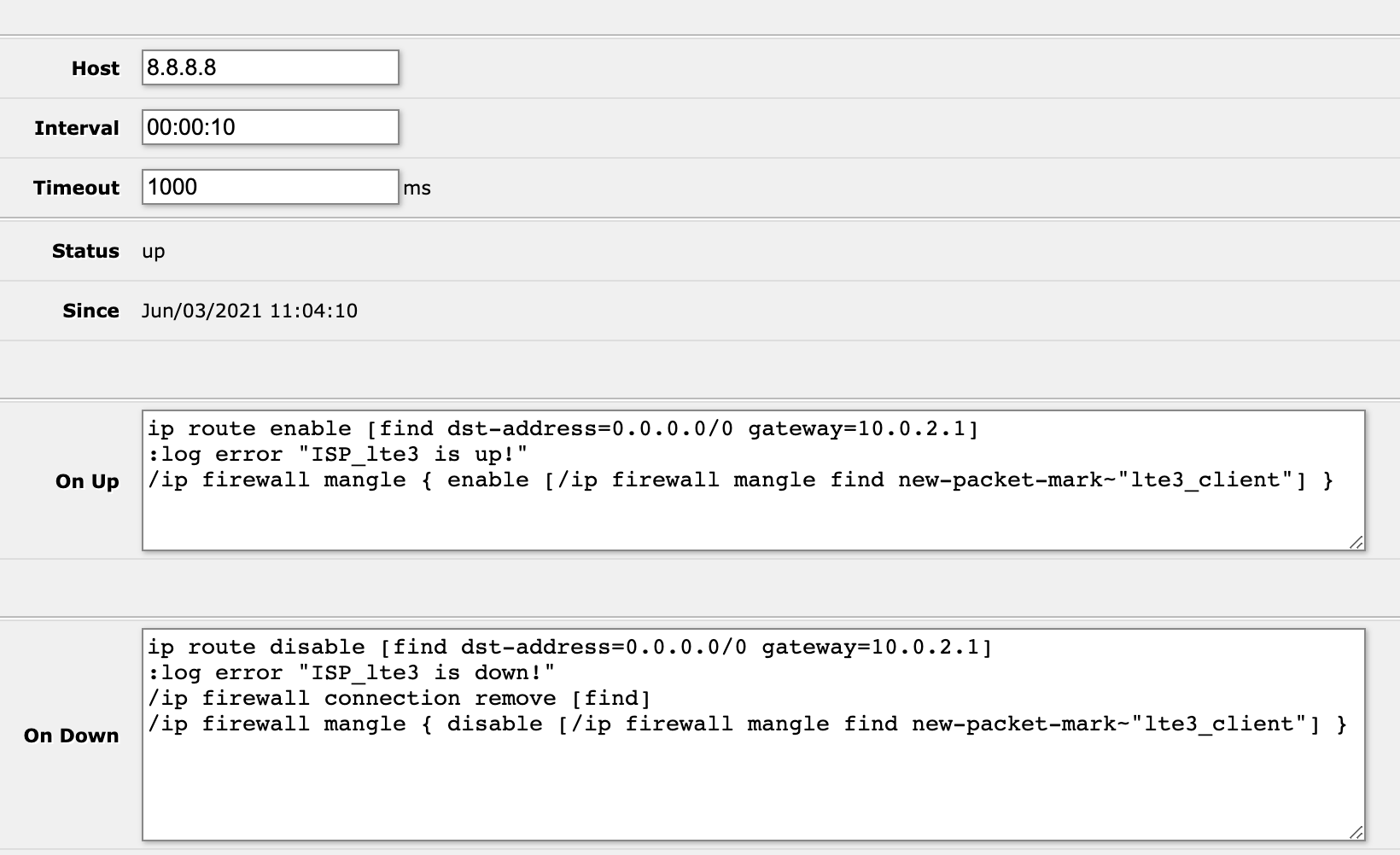
I decided to use a netwatch script because if the 10.0.2.1 router loses its Internet connection the route is still considered valid, with netwatch I could ping a internet address and make sure that the 10.0.2.1 router still has Internet access. I tried recursive routing failover but when I tested it I had some problems with it (sometimes it would not use the primary route even if that route was up).
I plan to try the following solution, thank you rextended, you even took the time to write me a script, you are great! I will post the results as soon as I can test this in a lab.
Hi anav, thank you for taking the time to review my whole config
1a) I don't think I need a bridge, WAN (10.0.2.1) is connected to ether1 (access port) and everything else is connected to ether2 (hybrid port)
1b) true, but some of the vlans use only static addresses
1c) some of the vlans were moved to the other router 192.168.10.1, that router serves as backup
1d) I only really need two, but it made my life easier to include another one while I was building the network, 192.168.102.0 is the VPN network.
You are right, I misunderstood this setting, thus allowing telnet access, I was able to remedy that with the firewall but now I understand this better
route 8.8.4.4 throught the secondary gateway and 8.8.8.8 through the primary (I thought this would be restrictive and 8.8.8.8 would only be routed to 10.0.2.1)
if 8.8.8.8 gets up enable the 10.0.2.1 route
the rest has to do with queues and is irrelevant
no I posted this before completing the setup, I didn't need it for the purposes of this post, but I'm sure you will find a more valid reason for me to get fired
I don't need one, the next router does NAT
I don't need them, there's only one hybrid port, bridge VLAN settings would make more sense if I used the router as a switch, I use a layer 2 switch for that
eth1 is WAN access and eth2 is hybrid
this is actually the case, I only use ether2
ether2 is also a WAN port albeit secondary and I don't need to clearly define it because I didn't use the default firewall configuration (in the final setup)
I believe I covered this when I finished the configuration and I don't feel that I need help with that
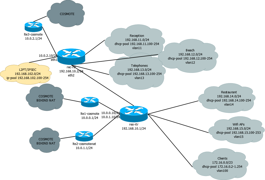
I dont quite get the network diagram,
Just to confirm you are showing two instances of the same router, to differentiate between the one dynamic WANIP (not natted - Cosmote top bubble)
and the two dynamic WANIPs that are natted lower two COSMOTE bubbles.
OR
Do you have two routers one for COSMOTE1 and a second router for COSMOTE2/3
Not what I would call a beginner network LOL.
That is some major work you have!! Bravo, I would be running away LOL
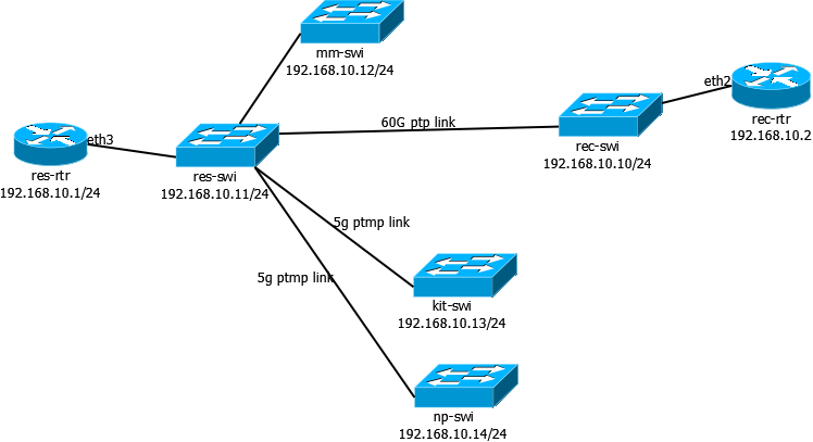
What i was really asking was, are the two routers sharing a subnet, as I am not conversant on how to best connect two devices as such.
Assuming you need to route Layer 3 some users or devices so they can see each other.
and sends the packet to 192.168.10.1 from eth2 (src address is unchanged)
192.168.10.1 (aka res-rtr) receives the packet from eth3
res-rtr uses a dynamic route created when I assigned the 10.0.0.10 ip to eth1 interface (src address is unchanged)
10.0.0.1 (aka lte1-cosmote) receives the packet and decides to reply (dst address is 192.168.11.101)
lte1-cosmote uses the route
So is the question how to setup failover for the router with two modems.
In basic terms
0.0.0.0/0 gwy=ISP1 gateway IP check-gateway=ping distance=5
0.0.0.0/0 gwy=ISP2 gateway IP distance =10
In this scenario all traffic will go out isp1 and if it goes down ISP2 will take over.
Normally this would be useless for the same ISP but I will assume that they are different sources and different equipment and dependencies that are different to make it a feasible idea.
Next you want to do recursive so it looks slightly different.
/ip route
add comment=PrimaryRecursive distance=5 dst-address=1.0.0.1/32 gateway=
ISP1gatewayIP
add comment=SecondaryWAN distance=10 gateway=ISP2gatewayIP
add check-gateway=ping distance=5 gateway=1.0.0.1
If you wanted to have the router check two different dns addresses for extra redundancy.
add comment=PrimaryRecursive distance=5 dst-address=1.0.0.1/32 gateway=
ISP1gatewayIP
add comment=PrimaryRecursive distance=8 dst-address=9.9.9.9/32 gateway=
ISP1gatewayIP
add comment=SecondaryWAN distance=10 gateway=ISP2gatewayIP
add check-gateway=ping distance=5 gateway=1.0.0.1
add check-gateway=ping distance=8 gateway=9.9.9.9
I value all your answers but I still don’t understand how this happens, is the rule disabled when the gateway is unreachable? Does the router fallback to the lowest distance 0.0.0.0/0 route when another route fails? Did I mess up my config? how does this work?
I took the liberty of rewriting this so I can understand it better
so if I understand this correctly you only test the isp1gateway and then use two external IPs to test against with accenting distances,
take a look at the solution proposed by rextended
notice the blackhole routes and the use of scope, (I have to read about scope to understand this), and If you follow the links provided you will see that the blackhole routes are important for this type of solution. I plan to test this out on a lab first because the router is now in production, netwatch although frowned upon, with my clumsy firewall rule is working.