Ok, I have set this.
I’ll update in a bit to see what happens.
Ok, I have set this.
I’ll update in a bit to see what happens.
So when I change the MAC Server settings to the admin interface list, I can no longer access the device from winbox PRIOR to removing all the 88 stuffs. Once I remove all the 88 items, then I can only access through IP, and only after I manually set my AdminPC IP to 101. When my adminPC connects and gets an auto IP, I can see the RB in winbox, but can’t connect. Once I manually set the IP, it no longer appears…
At least this is what I think I am seeing.
When I set VLAN Filtering on the bridge, I’m assuming that I set it to Admit all, or am I supposed to use a diff setting there?
All of my devices get set to the right IPs/VLAN addresses once their leases expire.
This is what my RB looks like in winbox. It has no IP?
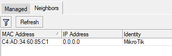
All the IP we have talked about have to be static, or the rules wont work.
So what you do, is go to the IP main menu selection.
Choose the DHCP Server sub selection
Then select Leases (third from the left at the top)
If your PC or device has been assigned the IP you want it to have then simply make it a static entry after opening it up.
If its already set static then that option is not visible.
If the device has a different IP address but you are happy with it, then set this IP as static, and then change any rules in the config so the IPs match.
Lastly you can add your device as an entry that you want IP address, but you will need the mac address, make this selection static then delete the old/wrong one.
Ok, so I don’t know what to ask/say. I’ve made all the IPs static: Synology, printer, Server, Admin, HTPC.
I can connect via winbox from AdminPC, but only using IP of the RB, not using MAC. I’ve configured the winbox settings the way you said, but I haven’t seen a difference either way.
Still no internet on other vlans and I haven’t been able to ssh into the server or get onto the synology webpage, even though I see them on the network.
I have backups made of each working and non-working configs so eventually we’ll find where it is blocked.
Thanks a bunch. Let me know what you think I’ve configured wrong?
vlanconfig-28mar.rsc (13.6 KB)
Multiple chains per radio are for MIMO and MIMO (theoretically) multiplies throughput (2x2 MIMO offers double throughput as compared to 1x1 MIMO).
To buzzed to make a reasonable try at the config had a quick look and seemed okay but tomorrow is another day/.
Not that confusing, if you let go the idea that WLAN definitions are bound to specific chains. They are not.
There is one radio per band in this device, like most devices, so there is one physical WLAN per band. (Exception is the “Audience” which has 2 radio’s in 5 GHz)
The radio is bound to a physical WLAN interface in RouterOS. One radio - one physical interface. If the radio has multiple chains, which each end on an antenna, then that radio can communicate over multiple spatial streams. E.G; a 2 chain radio, can communicate with a 2 chain/antenna device with 2 spatial streams. This means dubbeling the transmission throughput. (MCS14 is double the interface rate of MCS07, it uses 2 spatial streams) . Using 2 spatial streams is very common with tablets, smartphones, PC’s and MacBooks.
Within the physical WLAN configuration you set some parameters of the radio (channel width, TX power, channel or frequency, which chains used). Those values are shared with all the virtual WLANs defined on this physical WLAN. They cannot be set in the virtual WLAN. However things like mode (AP bridge, bridge, station bridge, …), SSID, security, WDS, etc can be different.from the physical setting. The transmission and reception shares the radio and its settings among the physical and virtual interfaces.
There is no way to split things like chains over different virtual WLAN’s. All virtual WLANs use the resources and settings of the master physical WLAN. The same for the frequency channels, only defined by the physical WLAN settings. There is no difference is performance or treatment of the physical or the virtual WLAN.
The advantage of the 4 chains in the 5 GHz band, is that if you communicate with another device that has 4 chains, you have 4 times the interface bandwidth compared to a single spatial stream. Other benefits are the fact that the radio will combine the received signal to get the best connection. And as far as beamforming is available in 802.11ac it will use beamforming with the antenna to transmit.
(Disadvantage of 4 chains is that the setting of the regulatory domain and the legal power limitations, will reduce the transmitpower with 6dB for 4 antenna, or 3 dB for 2 antenna (10*log3 for 3 antenna) But RouterOS lets you disable specific chains if you want, This is a setting for the physical WLAN only, and is also used in the virtual WLANs of course.)
Thanks for the great explanation! I appreciate learning how this MIMO and chains thing all works.
So, I’ve fiddled with it and haven’t got any further. I really am not good at this VLAN thing. I await those more knowledgeable than I!
Thanks.
Took me a while to find anything askew LOL… Fix the ones in red!!
/ip address
add address=192.168.101**.1/24** interface=“AdminPC VLAN101” network=
192.168.101.0
add address=192.168.5.0/24 interface=“Printer & Home WiFi VLAN5” network=
192.168.5.0
add address=192.168.10.0/24 interface=“Server/Lab VLAN10” network=
192.168.10.0
add address=192.168.15.0/24 interface=“Home WiFi Devices VLAN15” network=
192.168.15.0
add address=192.168.20.0/24 interface=“Synology & HTPC VLAN20” network=
192.168.20.0
add address=192.168.30.0/24 interface=“Google VLAN30” network=192.168.30.0
add address=192.168.40.0/24 interface=“Guest WiFi VLAN40” network=
192.168.40.0
add address=192.168.50.0/24 interface=“IoT VLAN50” network=192.168.50.0
Ok, so putting a 1 at the end of each of those addresses has made it able for me to connect to things from admin it seems. However, I believe that all VLANs have internet at this time. My IoT wifi still has internet.
Question I suppose I have is when I enable VLAN filtering on the bridge, do I use accept all, or do I use a different option?
Winbox is still only accessible via IP and not MAC.
I’m going to have to try and see how to test all the limitations I’ve put in. Lol.
Thanks!
29MarVLANs.rsc (13.6 KB)
Winbox is still only accessible via IP and not MAC.
Winbox MAC access is only for interfaces in the LAN interface list. Either add VLAN interfaces to the LAN interface list, or change this rule
/tool mac-server
set allowed-interface-list=LAN
/tool mac-server mac-winbox
set allowed-interface-list=LAN
Did you add in the last rule yet in the forward chain?
add action=drop chain=forward comment=“Drop all else”
When you do that all intervlan traffic at L3 unless allowed in your rules will be stopped as well as vlan50 access to the internet.
Oh, Derp! I forgot that one…
Ok, that went and did it.
Thank you!!! I have posted the final conf for anyone that wants to see.
FYI, the reason that my IoT devices are all offline is because the only item they need to speak to is the home automation server. Everything is controlled locally and thus even though I ‘could’ update the esp8266 OTA, I much rather not have them accessible. Just another hole plugged up in the network.
@anav, you are amazing, and as a fellow Canuck hats off to you!
JBHAllworking.rsc (13.8 KB)
We are living in interesting times where helping each other virtually and staying away physically is the way
So I’m still working on things.
I have my devices all connected and working on their respective VLANs. I can connect or not connect to the internet where I want.
I have my OpenHAB and MQTT running on port 8080 and 1883 respectively on the Server 20.20. I can connect to the MQTT from my adminPC but I cannot from the IoT devices VLAN50.
I cannot access my OpenHAB from AdminPC.
The VLAN IoT Access filter, is it working the way I seem to want it to? Devices on VLAN50 should be able to talk back and forth with Server on VLAN20. I think 1883 is probably the only port right now, but can someone show me how to make that rule work for one port and I can replicate it for others if the need arises?
Same seems to go for VLAN20 to VLAN101 when I’m trying to get to 8080, or 1880 (NodeRed).
Same config as previous post.
I do not know what you are referring to as MTT etc…
Remember if we allow traffic from A to B, then any requests from A to B ie expecting replies will be allowed back through.
What is stopped is any new traffic from B to A (that was not initiated on the A side – hope that makes sense.
So, I want the Server to be able to see the internet and the IoT devices to not. But I need the IoT devices and the Server to be able to exchange information between each other.
- MQTT: > https://en.wikipedia.org/wiki/MQTT > I use this for the wifi devices as clients to be controlled and report status to the Server as the host.
- NodeRed: > https://en.wikipedia.org/wiki/Node-RED > I use this to make rules to control my devices in the house. i.e: motion sensor to turn on a light. On the Server.
- OpenHAB: > https://www.openhab.org/ > The brains of it all, on the Server
I can confirm that things are all still running on my server, as I can reach them from the AdminPC, but I can’t seem to get the IoT devices to be able to login/report to the Server. The server should be able to talk back and forth with the IoT devices through MQTT (on port 1883). They need to login to the mqtt server and report periodically their statuses, and not always as a pull from the server but most of the time as a push. i.e. a temp sensor updating the new temperature in a room.
So how can I allow that specific traffic between IoT (VLAN50) devices and Server (VLAN10)? Is this going to compromise something else? Perhaps there is a different way we can set it up? Like putting the server in that vlan and only allowing it to connect to the internet but no other device there? Just shooting ideas…
Don’t listen to me… i’m potentially an idiot in this case. I am getting a little tired and making my own mistakes. I think everything is working as it should..
Thanks again everyone for all your great responses.
No worries, when not so tired, take a day off LOL, come back and we can hash out the smaller issues if any remain.
It all comes down to stating the use case requirements accurately and then we modify the config accordingly.
It is not uncommon after product delivery (software) that 80-90% of the errors are not bugs but errors in requirements.
Good Morning!
I thought I would try and post a new question here as I just ran into a requirement for one of my devices.
The Server that is mentioned above, I would like to open it up to the internet on tcp port 4042. I’ve installed the Dynu script and it seems to be working..(https://www.dynu.com/DynamicDNS/IPUpdateClient/Mikrotik-Dynamic-DNS)
I haven’t been able to write the correct Firewall or NAT rules to have it show as open.
I have not changed any rules or such, other than at the dynu link, and I did not use the doubleNAT version. How do I get this to work?
Hmm seems to be many scripts out there here is mine that I use with dyndns…
:global ddnsuser "yourusername"
:global ddnspass "yourpassword"
:global theinterface "ISP_interface"
:global ddnshost your.hostname.com
:global ipddns [:resolve $ddnshost];
:global ipfresh [ /ip address get [/ip address find interface=$theinterface ] address ]
:if ([ :typeof $ipfresh ] = nil ) do={
   :log info ("DynDNS: No ip address on $theinterface .")
} else={
   :for i from=( [:len $ipfresh] - 1) to=0 do={
      :if ( [:pick $ipfresh $i] = "/") do={
    :set ipfresh [:pick $ipfresh 0 $i];
      }
}

:if ($ipddns != $ipfresh) do={
    :log info ("DynDNS: IP-DynDNS = $ipddns")
    :log info ("DynDNS: IP-Fresh = $ipfresh")
   :log info "DynDNS: Update IP needed, Sending UPDATE...!"
   :global str "/nic/update\?hostname=$ddnshost&myip=$ipfresh&wildcard=NOCHG&mx=NOCHG&backmx=NOCHG"
   /tool fetch address=members.dyndns.org src-path=$str mode=http user=$ddnsuser \
         password=$ddnspass dst-path=("/DynDNS.".$ddnshost)
    :delay 1
    :global str [/file find name="DynDNS.$ddnshost"];
    /file remove $str
    :global ipddns $ipfresh
  :log info "DynDNS: IP updated to $ipfresh!"
    } else={
     :log info "DynDNS: dont need changes";
    }
}
Looks identical…
As far as the Server goes…192.168.10.10
You already have 2/3 requirements met.
FIREWALL FORWARD RULE that will allow incoming traffic to your server after negotiating the DST NAT RULE.
add action=drop chain=forward comment=
“defconf: drop all from WAN not DSTNATed” connection-nat-state=!dstnat
connection-state=new in-interface-list=WAN
SOURCE NAT RULE that keeps tracking of outgoing (originating behind the router) and then returning packets
/ip firewall nat
add action=masquerade chain=srcnat comment=“defconf: masquerade”
ipsec-policy=out,none out-interface-list=WAN
DESTINATION NAT RULE, is required to tell the router where the packets should go when arriving at the wan interface.
/ip firewall nat
add action=dst-nat chain=dstnat comment=“SERVER PORT FORWARDING”
in-interface-list=WAN protocol=tcp dst-port=XX to-address=192.168.10.10
IF you were looking for port translation then it would be like…
add action=dst-nat chain=dstnat comment=“SERVER PORT FORWARDING”
in-interface-list=WAN protocol=tcp dst-port=YY to-address=192.168.10.10 to-ports=XX