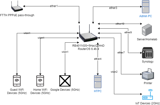
This is just to give you an idea of how I would tackle this setup.
The technical question I dont know how to answer is to best utilize the router switching.
I put the htcp and synology (heaviest traffic folks) on the same switch chip just in case and put the other devices on the other switch chip.
Basic starting point.
vlan2=adminPC (iot, google, home wifi devices, synology, serverhomelab, htpc, internet, printer, homewifi)
vlan5 -printer (internet?? )
vlan5-homewifi (internet)
vlan10 Server home/Lab (synology printer, iot, home wifi, internet)
vlan15=home wifi_devices (internet, (synology, printer))
vlan20=synology (internet only)
vlan30=google (internet only)
vlan40=guest wifi (internet only)
vlan50=iotdevices (homeserver only)
vlan 60 = htpc (serverhomelab, internet, printer, synology)
Create bridge = bridgehome
Create vlans with interface =bridgehome
Create dhcp structures for each vlan (ip address, dhcp-server, dhcp-server network, dhcp pool)
Create bridge port structure (assuming eth1 is for WAN)
eth2 - adminpc
eth3 - homeserverlab
eth4
eth5
++++++++++++++++++++++++++++++++++++++++ eth2-5 are one switch chip /6-10 on another/ sfp port is by itself.
eth6 - htcp
eth7 - synology
eth8 -
eth9
eth10
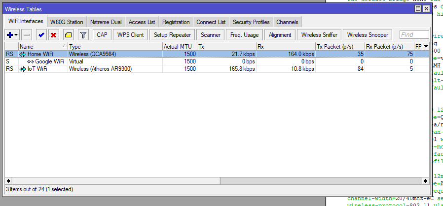
wlan1 5ghz home wifi
wlan2 5ghz guest wifi
wlan3 5ghz google devices wifi
wlan3 2ghz (iot devices channel 1)
wlan4 2ghz (home wifi devices channel 11)
Bridge ports describe ingress behaviour
so wlans entries include PVID and have frame-types=admit-only-untagged-and-priority-tagged [access ports]
so eth port entries to non vlan capable devices are same as wlans frame-types=admit-only-untagged-and-priority-tagged [access ports]
eth port entries to vlan aware devices (smart switches etc) ingress filtering=yes [trunk ports]
Bridge vlan behaviour (egress)
add a line for each vlanid, what needs to be tagged (bridge and trunk ports), untagged (wlan and access ports).
Default firewall rules to start.
Input chain
{default rules}
add action=accept chain=input comment=“Allow ADMIN to Router”
in-interface=vlan2 src-address=adminpcIP
last rule drop all else
Forward Chain.
{default rules}
[admin access] accept in-interface=vlan2 source ip= adminpcIP, out-interface-list=ADMIN (note2)
[synology, vlan2, vlan5, wifi devices, hptc, guest wifi, google access] accept in-interface-list=INTernet out-interface=wan (note6)
[server/home access] accept in-interface=vlan10 sourceip=serverhomeIP, out-interface-list=LAB (note3)
[wifi devices access] accept in-interface=vlan15 destination address-list=wifidevices (note4)
[iot access] accept in-interface=vlan50 destination-address=homeserverlabIP
[htpc access] accept in-interface=vlan 60 destination-address-list=HTPC note5
{default rules}
last rule drop all else
note2: Make an interface list
vlan5=ADMIN
vlan10=ADMIN
vlan15=ADMIN
vlan20=ADMIN
vlan30=ADMIN
vlan40=ADMIN
vlan50=ADMIN
vlan 60 =ADMIN
note3: Make an interface list
vlan5=LAB
vlan20=LAB
vlan50=LAB
Note4: Make a firewall address list
synologyIP=wifidevices
printerIP=wifidevices
Note5: Make a firewall address list
homelabIP=HTPC
printerIP=HTPC
synologyIP=HTPC
note6: Make an interface list
vlan2=INTernett
vlan5=INTernet (this includes home wifi and printer (did you want printer to access internet??)
vlan10=INTernet
vlan15=INTernet
vlan20=INTernet
vlan30=INTernet
vlan40=INTernet
vlan 60=INTernet