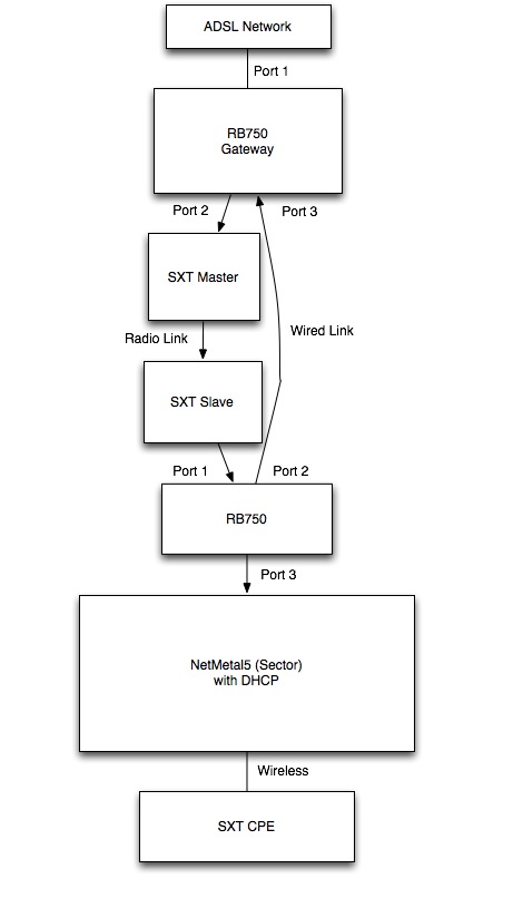
This is what I would like to create:
The final SXT should connect to the internet.
I’m connecting the RB750 both using wireless and wired connection to create a redundancy: I would like to see that when I remove the wired connection, it works using the radio one.
In your case one link would be wireless and the other wired. As the wired is less hops than wireless it should automatically prioritise the wired link.
P2P wireless interfaces should have their OSPF Network type=P2P to work correctly. Use Bridge->Station Bridge on SXT Wireless setup
Wired Ethernet interfaces should be network-type=broadcast.
Use /30 subnet’s between your devices on p2p links
Add a loopback (bridge) to each OSPF router and assign a unique loopback address to each e.g 10.255.255.x/32 and use this address as each routers OSPF Router ID.
On the last link (RB750) Instance set redistribute connected=yes and the AP could have a default gateway of whatever IP you assign to the RB750 ether3.
How can I offer to my users a public IP?
I would like to have a PPPoE server on the sector, and I would like to offer public IPs I have available on my external network to a CPE.
Public IPs are available on the gateway. I mean: I can set a public IP within my assigned classes on my gateway and it works, but I would like to make it possible also for customers.
How can I reduce the time OSPF requires to notice that a path is interrupted? If I reduce time intervals in OSPF settings I can’t see devices anymore…
dead-interval (time; default: 40s) - specifies the interval after which a neighbor is declared as dead. The interval is advertised in the router’s hello packets. > This value must be the same for all routers > and access servers on a specific network
hello-interval (time; default: 10s) - the interval between hello packets that the router sends on the interface. The smaller the hello-interval, the faster topological changes will be detected, but more routing traffic will ensue. > This value must be the same on each end of the adjancency otherwise the adjacency will not form
Thank you very much tania!
Do you have any example of how to assign public IPs to final users?
It’s the only thing I have to solve before implementing OSPF in my network!
Just set your Public IP pool on the PPPoE server. As long as your routing is working fine traffic will get there.
Turning on BFD will help a bit with failover times especially on links like the wireless where the link may go down but the physical interface on the RB750 won’t show it.
I’m not announcing any IP class. My provider does it for me.
If the network was bridged, I could just set a public IP on a device in the network and it would work.
Do you think it will work using OSPF?
If I would like to give a public IP to the CPE, what I should do? Simply assign it by using PPPoE?
Lets say the public IP space your ISP gave you is 10.0.0.0/24 and they route it to you via a /30 network at 172.31.0.0/30 telling you to use the IP 172.31.0.2 and that their side would be 172.31.0.1. All you need to do is put the IP range they assigned to you on your PPPoE server then make sure all our routers between the PPPoE server and your Internet border router know how to get to each other. Because your going to use OSPF as a dynamic routing protocol they should know about one another.
I understand I have to remove switches and add router in place, but… What address should I assign to each port of the router?
I mean: for P2P links I use a /30, but what about the router?
In the example I posted on the first post, what IPs should I assign to the last RB750 and the NetMetal?
You can use any subnet between your p2p links and the router - but choose a subnet that is only as big as necessary. So if you have used a /30 on the wireless interface of your p2p link and the p2p device is the only one connected to the router port then use another /30 between its ethernet interface and the router.
If the p2p is connected to a bridge with multiple devices (or switch group) then perhaps a /28 is appropriate.
For AP’s it is best to avoid using OSPF to publish client facing subnets actively. As clients connect and drop it creates new LSA’s across the whole network so better to not specify the client device subnet in /route ospf net and better to set the /rou ospf instance to publish connected instead. This way the AP’s subnet gets published as a whole and not on a per client address basis.
If you have an ethernet interface on your Mikrotik bridged via 3rd party wireless link (e.G SAF etc) then you will most likely need a /29 which will give 8 IP Adresses less 2 (broadcast and network) so 6 usable addresses. 1 for each Mikrotik and 1 each for your radios. As the radios may not support OSPF set their Gateway to point to the Mikrotik nearest where you are connecting from.
Network type=Broadcast should be OK if the link is a true L2 bridge but if you experience difficulty or instability then try setting the relevant interfaces to network-type=point to point
One thing i’d like to add is to consider using a different area for customer subnets as it limits any SPF calculations to that area which keeps bouncing links on the subscriber side from affecting LSAs and SPF calculations in the backbone area. Most large service providers use this design methodology when deploying OSPF on non-core subnets.
Thank you very much for your comments, they’re very helpful!
Do you think, on your experience, is it better to have an area for each subnet for users or only one area with all clients subnets?
And what about areas in the network? How much routers can be in the backbone area without overloading?
Speaking of routers and subnets… Do you think it’s better to have a /30 subnet between AP and each router port, or you think it’s better a /29 or bigger subnet where you put all APs in a tower? I think reduce broadcast traffic is better (so /30), but maybe too many subnets can overload OSPF?