I have an rb5009ug behind a Freebox Revolution (in bridge mode). For the Free TV to work (attached to the rb5009ug) it must get raw VLAN100 messages from the Freebox server. I tried putting a bridge on ether1 to ether2 but then the WAN on ether1 no longer worked because I can only put one bridge on ether1. I tried putting a VLAN interface between ether1 and ether2, which works but the frames are no longer raw and the Freebox TV no longer works. Is there a way of passing raw VLAN 100 data from the WAN on ether1 to the LAN on ether2?
Thanks for any information on the subject. I've passed several hours trying to work out a way to do this and I couldn't find a solution.
The RB5009 is a perfect device (due to the switch chip and how its ports are connected) to have a single bridge with ALL PORTS as member of the bridge, even the port you use for WAN (ether1).
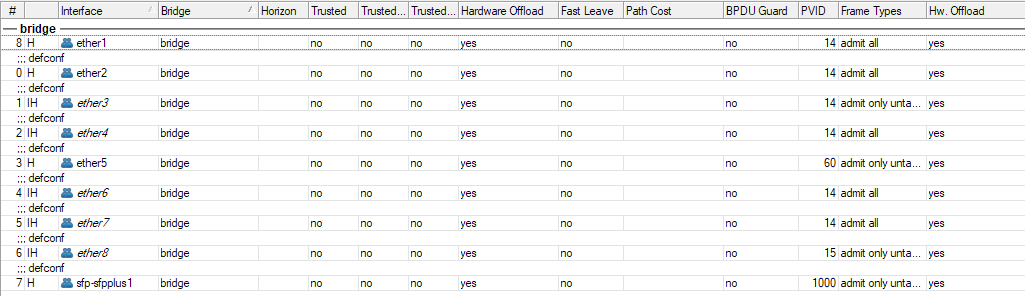
You add all ports to the bridge and configure Bridge VLAN Filtering. If your normal WAN is untagged on ether1, create a dummy vlan1000 interface on the bridge, that will be your WAN interface (where you setup DHCP client or PPPoE client). Make ether1 an access port of that VLAN 1000 (set PVID=1000 on ether1).
The VLAN 100 for IPTV will simply be tagged on ether1 on ether2.
Wouldn't it be easier to connect another Ethernet port of the Freebox device to, say, ether3 of the RB5009 and bridge it with ether2 unless, of course, more free ports are needed
Yes, the configuration would be easier, but you'll lose L2 hardware offload on that bridge. Only one bridge can be hardware offloaded, which means the CPU will have to do all the processing for the bridge between ether3 and ether2.
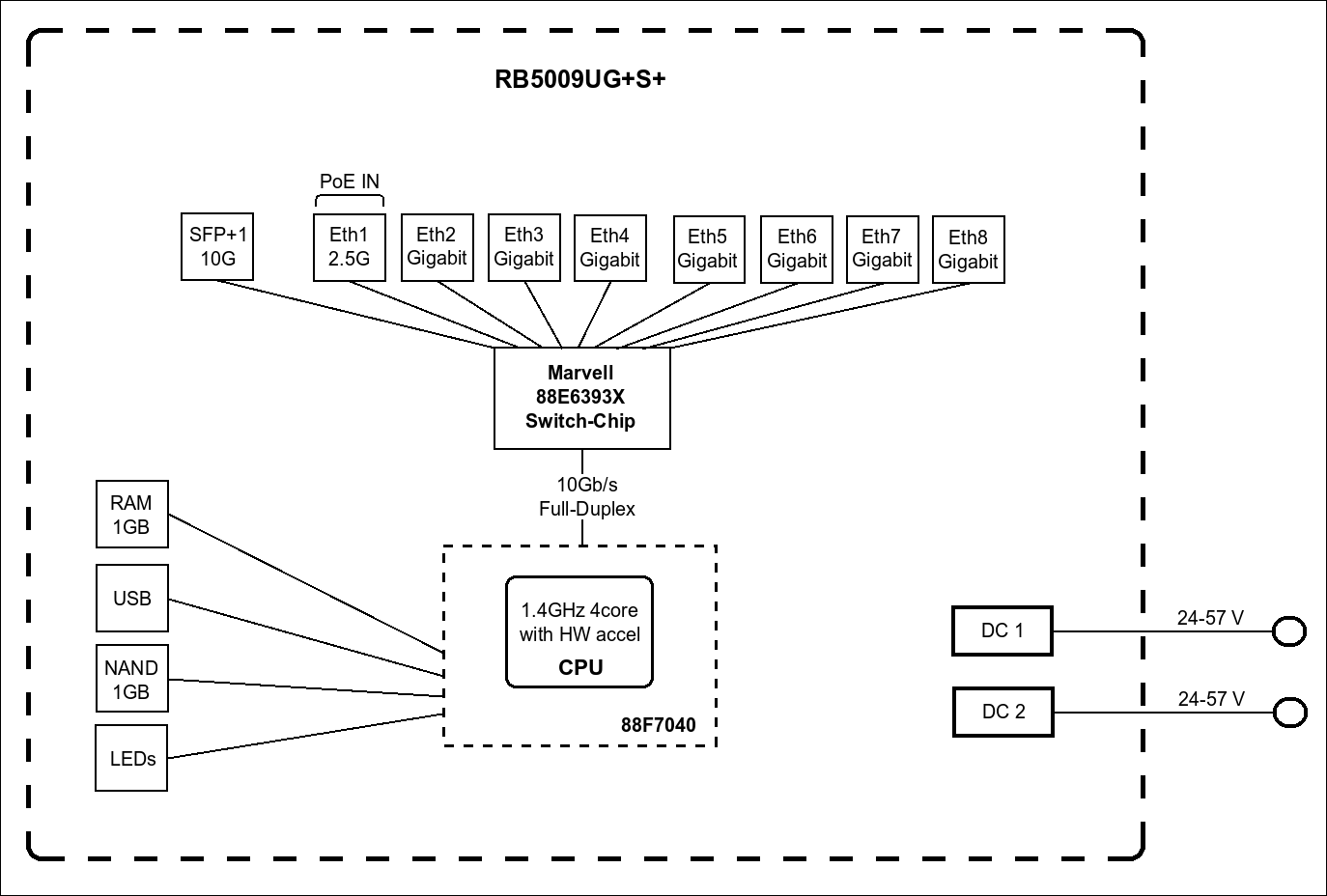
The RB5009 has all ports connected to the 88E6393X switch chip:
So putting all ports in the single bridge fully maps that bridge to the 88E6393X switch chip, and it handles VLAN tagging / untagging for you, as well as wire-speed switching within the VLAN (not layer 3 routing between VLANs, that needs the main CPU). The intra-VLAN traffics stay on the switch chip block and don't even need to use the 10Gbps link to the CPU in the diagram above. The IPTV traffic of VLAN 100 will use no CPU resource.
I have run my RB5009 for several years with the all-ports-in-single-bridge configuration, with the WAN port being sfp-sfpplus1, which is configured as access port of VLAN 1000. And VLAN 1000 is where I put the PPPoE Client interface:
So the WAN and LAN would have the same MAC address, I wonder, are there any issues for being such? Can the two be set to have different MAC addresses on the same bridge if need be?
There is normally no issue with the MAC address being the same, because the WAN VLAN and the other VLANs are separated Layer 2. My ISP requires cloning the MAC address of their modem router, so I set that MAC address on the bridge.
The only downside is when you have two or more WAN lines, and the ISPs all require specific MAC address. In that case you'll need to add a MACVLAN interface on the VLAN interface (it's possible since 7.20:
before 7.20 it was only possible to put that on the parent bridge or an ethernet port) and use the MACVLAN interface as the WAN interface with arbitrary own MAC address.
Thanks for your detailed reply.
However, this is using an intertface for doing the processing which (I believe) will mean that the message is packet-forwarded and not frame-forwarded. The Freebox uses ISP-specific headers which get lost when I do this and the Freebox TV doesn't reply. I see an ARPA request (from the Free server) for a private IP address (192.168.0.27, I think) and I suppose the that the header has an ISP flag saying only reply to this if you want this ISP's message. If I bridge directly WAN to the TV port then the TV works. If I pass through an interface then it no longer works. I could try to ask Free for another POP tv which just uses standard internet connections. The router is great, but the ISP-specific messages and the fact that I have other PCs on the same line as the TV makes it awkward. Yes, braveheartleo, I could have had a dedicated line for the TV but I'm in an old house with thick walls and the wire was put in when we did restoration work (so the wire is hidden in the ceilings and walls) so it would not be too easy to add a second dedicated line.
Then your only chance is to put all of the ports in one bridge and use VLAN filtering the way CGGXANNX described it. With a simple Wireshark packet capture you could check beforehand whether there is something ISP-specific in the VLAN tag (doubtfully since it's just a header that contains a VLAN identifier and at most CoS) and see whether it could be recreated with the Mikrotik by stripping the tag on ether1 ingress and reapplying it on ether2 egress and vice versa
The VLAN allows exactly this. It will bridge the ports you connect the TV to with the port connecting to the ISP device.
This is also not a problem. Transport the VLAN that the PC needs as tagged on the same cable. You can then configure the PC (works for Windows/Linux/macOS) to use this tagged VLAN (instead of the untagged frames).
PC and TV box can be connected to a dumb switch. Most dumb switches will let the frames through as it and will not mess up the VLAN tags.
I tried your method of putting the WAN entry into a vlan1000 interface on ether1 and it works perfectly. I'm still new to this router so I appreciate your help i(and diagram) in sorting out this problem.