Hello
Maybe in diffrent way
I got a fiber-optic cable and 30 IP addresses from my Internet provider (from 191.205.183.1 to 191.205.183.29 GW 191.205.183.30) and another additional address 84.1.81.254 - I don’t know why but for the internet to work I must indicate it as GW.
I am asking for help in configuring the mikrotik on the HP switch so that for address 191.205.183.30 I pointed to GW 84.1.81.253 and it worked
IP 84.1.81.254
MASK 255.255.255.252
GW 84.1.81.253
Most logical explanation to me would be that you got whole /27 subnet routed to you. If it’s the case, then 84.1.81.254/30 goes on WAN interface (connected to ISP) with gateway 84.1.81.253. And you can do anything you want with the other subnet.
As basic config, you can use whole /27, or split it into two /28s, four /29s, etc.
With /27, you have:
.0 - network address
.1-30 - usable addresses (one as gateway for connected devices)
.31 - broadcast
If you need more subnets, then with two /26s you’d have:
From what you posted, it’s not clear what you’re doing. At first sight it looks like you’re trying to have VLAN_2 as WAN and VLAN_1 as LAN, but then the subnets in routes are swapped. So you should clarify that, explain in more detail how is everything connected, etc.
I have a microtik CRS326
I would like to connect a link from ISP to a port e.g. eth1 (vlan1) and have a second subnet on the remaining ports eth2-24 (vlan2) so that I can control the bandwidth of the entire link from ISP and connected routers, servers, and address 191.205.183.30 as the gateway
And what part is not clear? You add 84.1.81.254/30 on WAN interface (the one connected to ISP), default gateway 84.1.81.253, and 191.205.183.30/27 on LAN interface (bridge). And that’s basic working config. Config for other devices is then 91.205.183.x/27 with default gateway 191.205.183.30.
Also, are there any actual vlans, or is it just like you call different interfaces?
Thank you very much for your answer.
Mikrotik cannot set the default GW in the address configuration.
I understand that this is done by adding route - how do I do it?
Where should I assign addresses to the port? Or maybe assign addresses to VLAN?
Should I make a bridge?
I’m not really sure what you’re trying to do. Are you?
This whole thing with vlans, is it possible that you don’t need it at all? So far I don’t see that it would be doing anything useful for you. Maybe you just want simple config like this?
I have another link from another ISP (VLAN3) there I do not have this problem because I do not have this additional IP address 84.x.x.x.
I will try to do this on one VLAN’s?
Maybe you should do something ineggo e.g. rules?
I’m still not sure if I understand your problem. The only difference is that with routed subnet you don’t bridge/switch the link from ISP with your VLAN interface, they stay as separate interfaces. Connecting subnet /30 goes on the one to ISP and /27 on VLAN. Other devices use as gateway whatever address from /27 you put on router.
Or if you’d prefer to have just one /27 with gateway on ISP’s router, you can try to ask them to do it like that. It wouldn’t be much different for them, they would just change subnet on their router, and it would save them four addresses (the /30 subnet).
I have 2 links from different ISPs and one device (CRS326) so I need to separate them.
I want to control the bandwidth of the ISP link and connected devices.
I need to get the option of any configuration - e.g. forward a link to the port (e.g. eth8, eth10) or transport it further (TRUNK to other switch or router devices).
This entry “add dst-address = 0.0.0.0 / 0 gateway = 84.1.81.253” would only apply to one ISP.
The question is how to run the route to this link with dual ISP addressing.
My idea that didn’t work is to split the connections into two different VLANs
Maybe it is enough to do it within one VLAN ?
Can the 84.x.x.x link be defined on the port and the 91.x.x.30 / 27 link on the VLAN port ?
I don’t know Mikrotik enough, maybe you had a similar topic and you will share a proven configuration
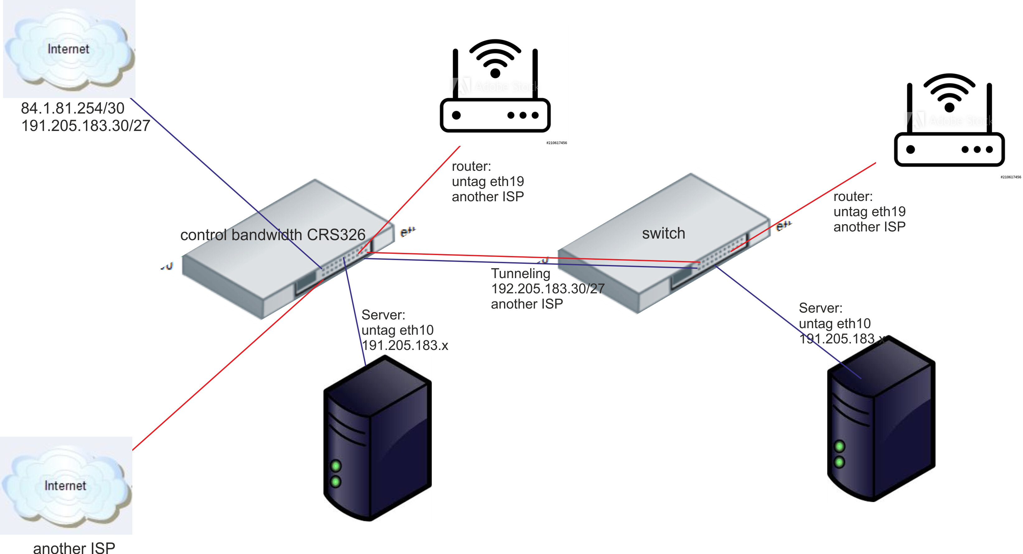
Thanks for the diagram it does help!!
so basically you wish to have a dual WAN setup such that
ISPX traffic goes onto VLANX network and devices
ISPY traffic goes onto VLANY network and devices.
These vlans will travel through a smart switch to those devices.
+++++++++++++++++++++++++++++++++++++++++++++++++++++
That is clear but to further program the router one needs to know:
a. what are your expectations if ISPX is not available (for any reason)
b. what are your expectations if ISPY is not available (for any reason).
(Dual ISPs provide redundancy as long as from different provider)
c. why is it that VLAN X traffic can only use ISPX and why is it that VLAN Y can only route through ISPY
(negates any kind of load balancing advantage of having two ISPs)
Hello
As I wrote in previous posts.
ad. a "I want to control the bandwidth of the ISP link and connected devices.
ad. b none, I have controlled it by the interface traffic from distawct ISP
ad. c this will be done by devices connected further
The only problem I have is with the routing setting, maybe the role or other solution with the link from the ISP provider with dual addressing.
Others combine ISPs with a single addressing, it works fine for me
Let me ask it another way then as the answers are not clear.
a. If ISP X is not available do you want USERS on LAN X to access the internet through ISP Y (tap into the Y ISP stream)
b. If ISP Y is not available do you want users on LAN Y to access the internet through ISP X (tap into the X ISP stream)