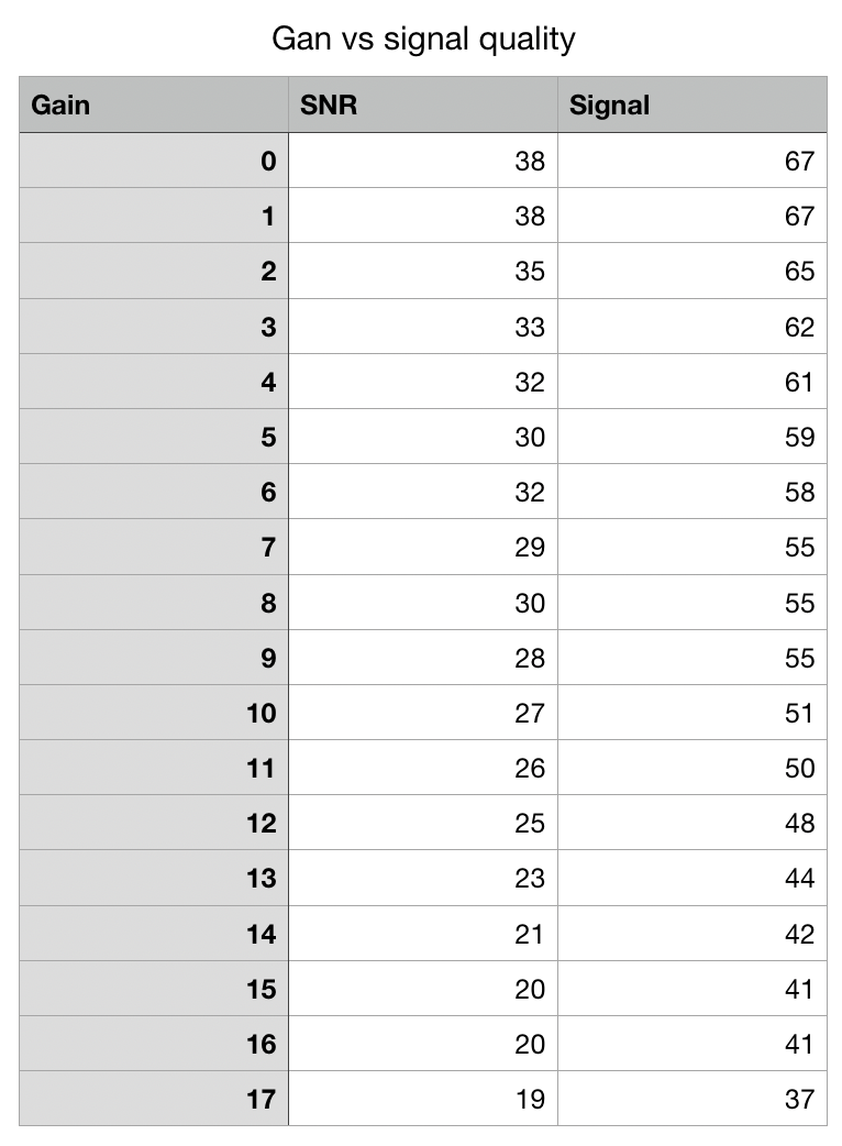
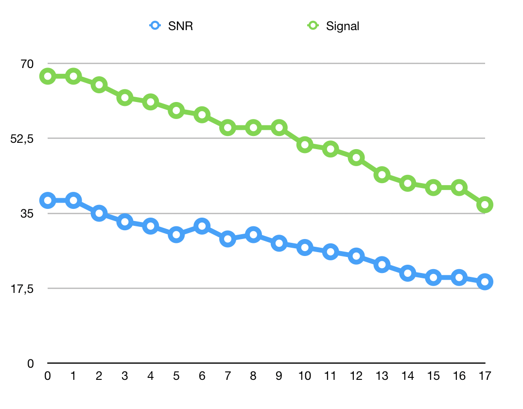
I did some practical measurements to see how will signal fall with Antenna Gain setting.
I tested these for implementation in a CAPsMan network using RB2011 that I had on hand and WiFi Signal application 4.2.2.
There was essentially no noise around and the AP vas close measuring computer. The idea was to find general relation.
You can cut signal up to value of 17. When you are close to AP stuff work as on other powers, but as you move away, signal quality falls rapidly, which is expected and welcome (in a CAPsMan network).
Here is the graph and data if anyone is interested.
What is the practical signal gain level that you use for CAPsMan network (I use CAP lite a lot)?
Setting a higher antenna gain will reduce the regulatory limited power with the same amount in a linear way..
(But the regulatory limit is reached with a lower transmit power for higher MCS values! So TX power depends on the MCS used.)
@Cameroon: yes there is no creation of energy out of nothing. Antenna’s do not create energy, but they concentrate the radiational energy in a specific direction. The pure sferical radiation does not exist, that would be the antenna gain of 0 dBi. Omnidirectional antennas create a donut-shaped distribution of energy around the antenna. A single element is typical 2 to 3 dBi concentration in the donut direction.(There is no energy in the direction the antenna itself is pointing). A 2 segment antenna will be 5 to 6 dBi , and a flatter donut shape. A 3 element antenna is around 8 to 9 dBi and an even flatter donut, but with some sidelobes) A directional antenna like in the SXTsq or Mant sector antenna are not omnidirectional around the antenna material, but only cover a sector of the circle. The smaller the sector the higher the energy concentration. For the SXTsq it is 16 dBi.(40 times). This is typically done with an array of 9 or 16 antenna’s.
The regulation dictates the maximum EIRP for an antenna/radio combination. That is the energy level in the peak direction, but supposed to be uniformly distributed omnidirectional (i=isotropic). That means for an SXTsq with an antenna gain (concentration) of 16 dBi, that for a maximum allowed energy transmission of 20 dBm, the radio can only be set at 4 dBm.
That is what RouterOS is doing, to conform the regulations (FCC, ETSI, CE norm …). If for a frequency the allowed maximum is 20 dBm, it will reduce the radio to 17 dBm , if the known antenna gain (concentration) is 3 dBi. If you now tell RouterOS in the configuration file that the antenna gain is 17dBi (while in reality it is 3 dBi) , then RouterOS will reduce the transmit power to 3 dBm (=20-17). The actual EIRP will be 3 dBm from the radio + 3 dBi from the antenna gain (concentration) or an EIRP of 6 dBm. That is 14 dBi lower than the allowed maximum.
That is how you can control the transmit power of a MKT wiifi device, by entering a higher, or let’s say fake, antenna gain value, and leaving the TXpower setting on default. Why this way? Because setting the correct TXpower to be within the legal limits is complicated. If you use 2 radio’s you have to set it 3dBm lower (3dB = 2x). For the higher MCS settings there is more energy in the sideskirts of the frequency spectrum, and therefore then the TXpower must be set lower.
That’s not how I read the data in Wireless specifications. The hard fact (a sad one) is that most low-cost RF power amplifiers are not entirely linear in whole rated power output range, which means that when amplifying more complex signal (e.g. modulation 64QAM as used in MCS7) the practical maximum output power with distortion below harmful level is lower than when amplifying simpler signals (e.g. BPSK used with MCS0). This effect is commonly called power backoff.
The TX power table (data rate / MCS versus Tx power) for MT devices reflects that.
Now when max Tx power (at the exit of RF PA) required is lower than rated maximum (e.g. when it has to be lower due to higher antenna gain), then device is able to transmit all MCSes with same TX power and thus can offer same coverage for all data rates (when transmitting with high power affected by power backoff device offers better coverage for lower datarates due to higher Tx power). For example: hAP ac2 on 2.4GHz can transmit with 27dBm at low datarates and 23dBm at MCS7. If country limits EIRP to 30dBm and antenna gain is 2dBi, then device will try to transmit at maximum power and will thus use lower Tx power for higher datarate. If, OTOH, country limitation for EIRP is 20dBm with antenna gain of 2dBi (or country limitation is 30dBm and one sets antenna gain to 12dBi to lower Tx power by 10dB), then RB will drive RF PA to max output power of 18dBm … which is available for all supported datarates / MCSes.
The other story is zhen Rx sensitivity, which affects coverage with certain datarate as well. For most RF devices the sensitivity for higher datarates is worse meaning signal strength has to be higher. And this is the factor which affects data throughput much more than the before explained power backoff … the difference in sensitivity of hAP ac2 between basic datarate and the best one is 27dB (power backoff difference is 4dB).
Hi MKX, this is also what I understood as well from the Wireless Specifications_:“The hard fact (a sad one) is that most low-cost RF power amplifiers are not entirely linear in whole rated power output range, which means that when amplifying more complex signal (e.g. modulation 64QAM as used in MCS7) the practical maximum output power with distortion below harmful level is lower than when amplifying simpler signals (e.g. BPSK used with MCS0). This effect is commonly called power backoff.
The TX power table (data rate / MCS versus Tx power) for MT devices reflects that.”_
Until I listened to this recently in a search for answers “See from minute 36 till 41; https://www.youtube.com/watch?v=pmtB3LlwquA (MUM EU 2015 What you see is not always what you get)”. I tend to believe the competence of Ron Touw. So maybe I should look further to clear out if it is power lack of the radio, or it is the radio going broader in spectrum with the higher MCS because of a cheap radio and more harmonic distortion, or because of the spectral mathematics (the energy is not at at the central frequency but in the side lobes which alter by the encoding used)
So I’m not sure if with this … “Now when max Tx power (at the exit of RF PA) required is lower than rated maximum (e.g. when it has to be lower due to higher antenna gain), then device is able to transmit all MCSes with same TX power and thus can offer same coverage for all data rates (when transmitting with high power affected by power backoff device offers better coverage for lower datarates due to higher Tx power). For example: hAP ac2 on 2.4GHz can transmit with 27dBm at low datarates and 23dBm at MCS7. If country limits EIRP to 30dBm and antenna gain is 2dBi, then device will try to transmit at maximum power and will thus use lower Tx power for higher datarate. If, OTOH, country limitation for EIRP is 20dBm with antenna gain of 2dBi (or country limitation is 30dBm and one sets antenna gain to 12dBi to lower Tx power by 10dB), then RB will drive RF PA to max output power of 18dBm … which is available for all supported datarates / MCSes.” . …we still comply with the regulation. If we faked the antenna gain to lower the TXpower transmission to an EIRP lower than the regulatory limit to get a cleaner signal , then we still comply when using the flat power curve as we have some headroom. If we get a clean signal at these higher MCSes then, is still the question. It depends on the root cause of the lower power ( weak radio, bad harmonics at higher MCS in this radio, pure encoding and spectrum mathematics). I don’t have the answer.
Is this 27 dBm the same kind of information as in the already mentioned table with MCS/SNR/RSSI , requiring higher SNR and as such higher RSSI to decode the higher MCS modes?
Great presentation. However, Ron’s presentation doesn’t get into the reasons for the broadening the radiated spectrum. I tend to think that it’s still incapability of (cheap) RF PAs to cope with complex modulations and thus generating distortions. Mind that distortions don’t have to be only in-band, can be also out-of-band. The most simple case of amplifiers not being capable of following the original signal shape is Heaviside’s function (step function) … not many PAs can handle it without considerable distortion (smoothing) of the “corners”.
Is this 27 dBm the same kind of information as in the already mentioned table with MCS/SNR/RSSI , requiring higher SNR and as such higher RSSI to decode the higher MCS modes?
Seems that it’s about the same thing, just seemingly not in the same units somehow.
When observing such tables one has to keep in mind that one thing is theory (and in theory receiver is only limited towards low power signals with thermal noise level) and another thing is implemented solution (practical thermal noise floor has higher level due to receiver heating, then there are noise numbers of all elements in Rx path, including passive elements such as antennae, antenna feeders, …). Due to this, Rx sensitivity can vary between different WiFi chips and gets worse if implementation of the rest of Rx path is sub-optimal. E.g. Ron mentions attenuation of pigtail which is not constant over spectrum used.