Sofware VLAN/Bridge on RuterOS explained.

Thanks again.

It seems to work fine without the last changes, so did I break some with it?

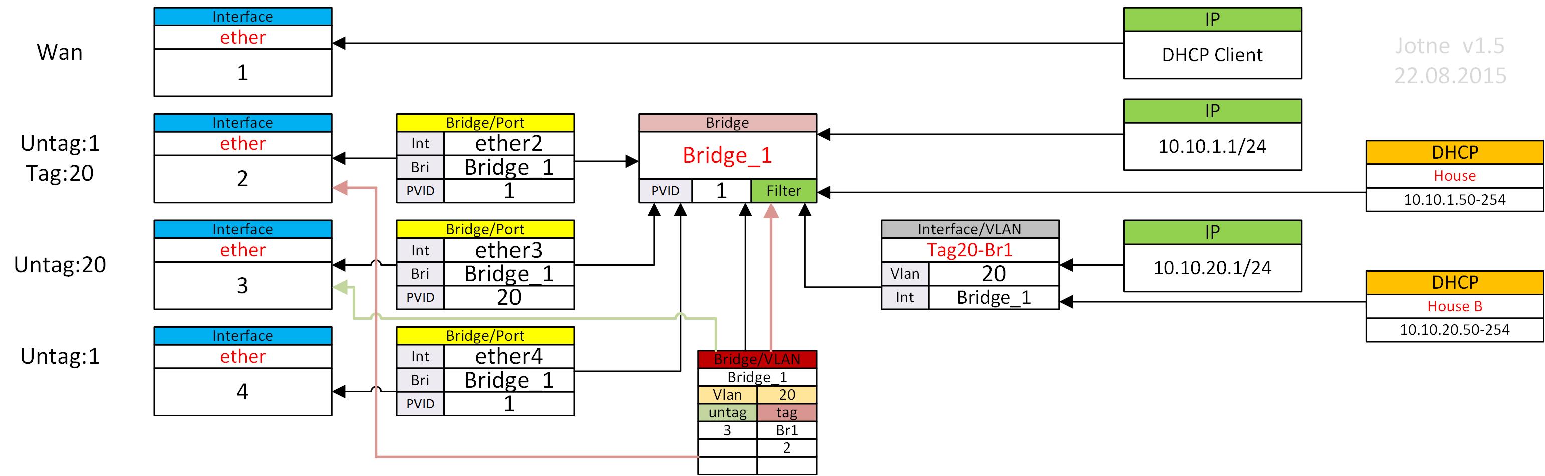
Will try to make a Visio with some layer to handle it:
Test15.jpg
PS, just found another great pluss doing it this way with the new bridge implementation (>=6.41).
If you need more that one VLAN tagged on port with old solution, you need one Bridg/Port pr VLAN.
With Bridge/VLAN you can specify ranges of VLAN like this:

vlan-ids=100-115,120,122,128-130

Are you sure it really does? Without vlan-filtering=yes, the tagging/untagging on interfaces does not work. So in your case:

  • tagless frames coming to ether2 and ether4 get in and stay tagless on the Bridge_1 - this is what happens with both settings of vlan-filtering
  • frames tagged with VID 20 coming to ether2 get in and stay tagged, so the tagged side of /interface vlan vlan-id=20 receives them tagged - this is what happens with both settings of vlan-filtering
  • tagless frames on ether3 get tagless to bridge, but once they are in, I suspect they are handled at L3 anyway - so it works differently than you expect
  • tagged frames sent from the IP address associated to /interface vlan vlan-id=20 get remain tagged as they leave via ether3, but if a Windows machine is connected to that interface, it untags them on reception because that’s how most Windows network interface drivers work - so it works differently than you expect

Sniffing packets on ether3 into files with vlan-filtering=yes and vlan-filtering=no (on the Mikrotik, not on the connected PC because there you would see the VLAN tags already stripped) and opening those files using Wireshark should show you the difference.


This is an advantage if you care about vlan filtering as such, i.e. when you want to drop ingress frames whose VID is not permitted on the ingress port. If you don’t, frames tagged with any VID are forwarded between all member ports of a bridge if vlan-filtering=no.

I just want to comment to thank you both. I’m thoroughly enjoying this discussion.

I too have been plagued by the variables of interface, bridge, vlan, and switch configurations when implementing VLANs. This discussion is definitely helping me understand it better.

Yes, thank you both for the education. I didn’t really need it, but it was interesting. I have a different solution. I use routers EXCLUSIVELY as routers and switches as switches. Each port of my routers is either a single LAN or a VLAN trunk port. Never does any LAN or VLAN appear on more than one physical port. Each port in turn connects to a port of a managed switch (CSS326-24G-2S).

The same exercise is needed when configuring RB running ROS if that RB is to be used as smart switch. Not that I would recommend that since HW offload is disabled and all traffic is dealt with by CPU.

As I said, the two routers are only used as routers. All switch functions are handled by the CSS326.

With that said, the education in this thread was very interesting. thank you!

Very nice post but one thing is missing,
Final configuration export with your last picture..

Absolutely great THREAD.-- Thanks to:
@Jotne
@sindy

IMO, @k6ccc approach is the one that I would encourage most to follow – in that way YOU are maximizing value and performance consistently.

I use routers EXCLUSIVELY as routers and switches as switches.
Each port of my routers is either a single LAN or a VLAN trunk port.
Never does any LAN or VLAN appear on more than one physical port.
Each port in turn connects to a port of a managed switch (CSS326-24G-2S).

IMO, the biggest improvement – performance wise – that MikroTik could add to [RouterOS] for the hEX and for hAPac2 is to to incorporate fq_codel and/or WireGuard

What a great thread. I hope my revival of it is relevant.

I am failing in trying to set the new way of vlan bridging. I have followed your guide and this RouterOS - RouterOS - MikroTik Documentation (v6.41+ way of vlan bridging).

The problem is this code.

/ip dhcp-server
add address-pool=dhcp_pool10 disabled=no interface=VLAN10 name=dhcp10
add address-pool=dhcp_pool20 disabled=no interface=VLAN20 name=dhcp20

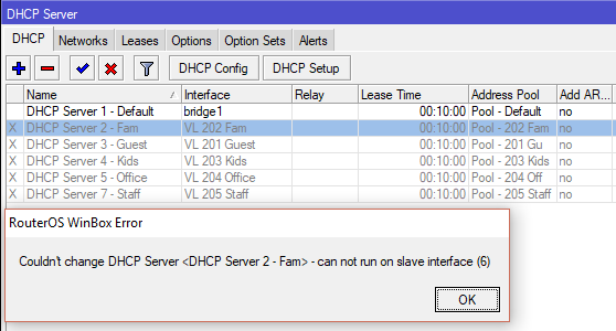
My DHCP Server when assigned to a VLAN interface returns an error "Cannot run DHCP Server on Slave Interface", and disables itself. I am running ROS v6.43.2.


What am I doing wrong?

\

The is the overall code as instructed in the mikrotik wiki, to save you time from loading the link.


/interface vlan
add interface=ether1 name=VLAN10 vlan-id=10
add interface=ether1 name=VLAN20 vlan-id=20

/ip address
add address=192.168.10.1/24 interface=VLAN10
add address=192.168.20.1/24 interface=VLAN20

/ip pool
add name=dhcp_pool10 ranges=192.168.10.2-192.168.10.254
add name=dhcp_pool20 ranges=192.168.20.2-192.168.20.254

/ip dhcp-server
add address-pool=dhcp_pool10 disabled=no interface=VLAN10 name=dhcp10
add address-pool=dhcp_pool20 disabled=no interface=VLAN20 name=dhcp20

/ip dhcp-server network
add address=192.168.10.0/24 dns-server=8.8.8.8 gateway=192.168.10.1
add address=192.168.20.0/24 dns-server=8.8.8.8 gateway=192.168.20.1

This is my code, I've followed the guide and your posts as closely as I can. There is nothing in my code that is different than the wiki. I find it hard to swallow that the wiki is incorrect. It must be somewhere in my setting.


/interface vlan
add interface="wlan2 - 5g" name="VL 201 Guest" vlan-id=201
add interface="wlan2 - 5g" name="VL 202 Fam" vlan-id=202
add interface="wlan2 - 5g" name="VL 203 Kids" vlan-id=203
add interface="wlan2 - 5g" name="VL 204 Office" vlan-id=204
add interface="wlan2 - 5g" name="VL 205 Staff" vlan-id=205

/ip address
add address=192.168.88.1/24 comment="Default Config" interface=ether2-master network=192.168.88.0
add address=192.168.201.1/24 interface="VL 201 Guest" network=192.168.201.0
add address=192.168.202.1/24 interface="VL 202 Fam" network=192.168.202.0
add address=192.168.203.1/24 interface="VL 203 Kids" network=192.168.203.0
add address=192.168.204.1/24 interface="VL 204 Office" network=192.168.204.0
add address=192.168.205.1/24 interface="VL 205 Staff" network=192.168.205.0

/ip pool
add name="Pool - Default" ranges=192.168.88.100-192.168.88.199
add name="Pool - 201 Guest" ranges=192.168.201.100-192.168.201.199
add name="Pool - 202 Fam" ranges=192.168.202.100-192.168.202.199
add name="Pool - 203 Kids" ranges=192.168.203.100-192.168.203.199
add name="Pool - 204 Office" ranges=192.168.204.100-192.168.204.199
add name="Pool - 205 Staff" ranges=192.168.205.100-192.168.205.199

/ip dhcp-server
add address-pool="Pool - Default" disabled=no interface=bridge1 name="DHCP Server 1 - Default"
add address-pool="Pool - 202 Fam" interface="VL 202 Fam" name="DHCP Server 2 - Fam"
add address-pool="Pool - 201 Guest" interface="VL 201 Guest" name="DHCP Server 3 - Guest"
add address-pool="Pool - 203 Kids" interface="VL 203 Kids" name="DHCP Server 4 - Kids"
add address-pool="Pool - 204 Office" interface="VL 204 Office" name="DHCP Server 5 - Office"
add address-pool="Pool - 205 Staff" interface="VL 205 Staff" name="DHCP Server 7 - Staff"

/ip dhcp-server network
add address=192.168.88.0/24 comment="Default Config" dns-server=192.168.88.1 gateway=192.168.88.1 netmask=24
add address=192.168.201.0/24 gateway=192.168.201.1 netmask=24
add address=192.168.202.0/24 gateway=192.168.202.1 netmask=24
add address=192.168.203.0/24 gateway=192.168.203.1 netmask=24
add address=192.168.204.0/24 gateway=192.168.204.1 netmask=24
add address=192.168.205.0/24 gateway=192.168.205.1 netmask=24

/interface bridge port
add bridge=bridge1 comment="Default Config" interface=ether2-master
add bridge=bridge1 comment="Default Config" interface="wlan1 - 2.4g"
add bridge=bridge1 comment="Default Config" interface="wlan2 - 5g"
add bridge=bridge1 interface=ether3
add bridge=bridge1 interface=ether4
add bridge=bridge1 interface=ether5
add bridge=bridge1 interface="VL 201 Guest"
add bridge=bridge1 interface="VL 202 Fam"
add bridge=bridge1 interface="VL 203 Kids"
add bridge=bridge1 interface="VL 204 Office"
add bridge=bridge1 interface="VL 205 Staff"

/interface bridge settings
set use-ip-firewall=yes use-ip-firewall-for-vlan=yes

Update: I found my mistake. The VLAN interface cannot be a member of bridge1. The following code should be deleted.


add bridge=bridge1 interface="VL 201 Guest"
add bridge=bridge1 interface="VL 202 Fam"
add bridge=bridge1 interface="VL 203 Kids"
add bridge=bridge1 interface="VL 204 Office"
add bridge=bridge1 interface="VL 205 Staff"

I won't delete my post to bump this thread. Kudos to a great thread.

I've just locked myself out of my hap-ac2 by tagging the wrong vlan to the wrong interface and I've had to hard reset the unit. Coming from unifi where vlan setup and switch deployment across the enterprise are but a few clicks away, I feel like I'm into some hardcore S&M shit with Mikrotik (I'm perversely enjoying it).

Using the Safe Mode button in Winbox/WebGUI or Ctrl-X in CLI lowers the levels of adrenaline very significantly.

Amen to that brother, and keeps the family from tearing strips of ones hide!!

Hi asphri…
Regarding your post…
The plan falls apart at the getgo, you only need one bridge.
It appears that you have two bridges, the first named Bridge1 and the second inferred from /Interface Vlan - “wlan2 - 5g”

There I recommend to keep it simple
Use Bridge1 only and this changes your /interface VLAN as follows:

STOP* Put your router in SAFE MODE :slight_smile:

/interface vlan
add interface=“Bridge1” name=“VL 201 Guest” vlan-id=201
add interface=“Bridge1” name=“VL 202 Fam” vlan-id=202
add interface=“Bridge1” name=“VL 203 Kids” vlan-id=203
add interface=“Bridge1” name=“VL 204 Office” vlan-id=204
add interface=“Bridge1” name=“VL 205 Staff” vlan-id=205

Remember here is where we create vlans and associate the VLANs to the bridge.

This problem really rears its ugly head at this step.
/interface bridge port.

To recap when selecting the Bridge Menu, one can ignore the first Bridge Tab, the default tab when selecting Bridge from the left hand menu in WInbox (unless need to create a new bridge or delete one etc.) The order being, hit the ports tab first, the vlan tab second and then come back to the bridge tab on the bridge menu.

Bridge Ports are where you add physical ports to the correct Bridge and you DO NOT associate here VLANs to the bridge (that is what the VLAN tab is for).

Therefore it should look like this
/interface bridge port
add bridge=bridge1 comment=“Default Config” interface=ether2-master
add bridge=bridge1 interface=ether3
add bridge=bridge1 interface=ether4
add bridge=bridge1 interface=ether5

Note: If you wanted a separate LAN, lets say a DMZ you could put it on ether 4 and not on the bridge and you would eliminate it under bridge ports.
Similarly you should note that no WAN interfaces belong here either (for normal setups).

Next, you need to delineate the VLAN TAB
This feels like to me almost like assigning the Bridge to be like a trunk of sorts.
At least in Winbox you select doubleclick on the name of your bridge and fill out the menu from top to bottom:
Bridge: Correct Bridge (already filled in cause you clicked on it)
VLan IDs: Add a separate line for each VLANID in your case 5 separate entries.
Tagged {Entities}: Add a separate line for each one, meaning any physical port that is carrying at least one VLAN s and the bridge itself in your case Bridge1 and most likely ether2-5
Done!

Now you can go back to the First Bridge Tab, double click on the bridge name again and from that popup menu select a new/different VLAN TAB;

STOP **** Ensure SAFE MODE IS ON!!

SImply check VLAN filtering to apply the rules entered thus far.

You dont mention /interface list and what I do is
lan - bridge (includes the bridge and all ethernet interfaces you have already associated to the bridge)
lan -ether4 (for an example if running a separate lan like a dmz off that port)
lan - vlan1
lan - vlan2
etc.
wan - isp1
wan - isp (if you have two isps for example)

Since the lan interface is useful in firewall rules its good to have the entries here.

I think that covers most of it.

Oh one more thing this setting/text makes no sense to me because I dont see them on my rsc files nor are they visible in winbox.

/interface bridge settings
set use-ip-firewall=yes use-ip-firewall-for-vlan=yes
Still trying to figure this out.
Is it possible to post a small working example ?

We can create one. You have honour of supplying description of a simple scenario.

Also checking in as someone who is struggling to get VLANs working.

My use-case is trying to isolate traffic from a virtual wireless interface, with separate box for WAN.
How do people create pretty network diagrams?

box-1:

  • wireless interface “wlan” for ‘normal’ non-vlan, untagged, etc. wireless usage
  • virtual wireless interface “wlan-guest” with vlan-id=50 and vlan-mode=use-tag
  • ether1 goes to box-2
  • ether2 and ether3 for ‘normal’ non-vlan, untagged, etc. wired usage

box-2:

  • wireless interface “wlan” for ‘normal’ non-vlan, untagged, etc. wireless usage
  • ether1 goes to box-1
  • ether2 and ether3 for ‘normal’ non-vlan, untagged, etc. wired usage
  • SFP WAN port for internet

Assumptions:

  • normal users are all on one big LAN 10.0.1.0/24 and can ping each other, even across box-1/box-2, and can access internet
  • “guest” users are on 192.168.50.0/24, can’t ever talk to normal users, but can access internet
  • box-2 is DHCP server for 10.0.1.0/24, i.e. normal users
  • box-2 does NAT from 10.0.1.0/24 and 192.168.50.0/24 to internet
  • internet traffic is vlan-less/untagged
  • RouterOS 6.43.8

Questions:

  • the cable between box-1 and box-2 would have vlan-less, untagged traffic for normal users, and vlan-50-tagged traffic for guest users?
  • is possible to have box-1 do DHCP for guest users? (seems the intuitive choice to me)
  • how does box-2 tag and route 192.168.50.0/24 traffic to box-1?

@Jotne uses Visio. Others use ASCII art (and lots of imagination) :wink:


  • Yes.
  • Either of boxes could do. I’d keep high-level config to single box (box-2 in this case) just to have configuration in single place.
    Plus: if DHCP server for guest VLAN is on box-2, then box-1 (management part of it) is not exposed to guests at all. If box-1 would have IP interface for guest network, you’d have to take care not to route between the both interfaces (I assume you want box-1 to have IP connectivity in normal LAN), so you’d have to maintain two firewalls…
  • It doesn’t route, it uses VLAN tags, switch makes sure packets arrive at desired destination. To make it work, VAP needs to be tagged and the trunk port towards box-2 as well (in addition to untagged). On box-2, trunk port towards box-1 needs same config as trunk port on box-1, then box-1 needs a vlan interface for tagged traffic … which is where L3 routing/firewalling starts to happen. And DHCP server for guest VLAN (if you kept it on box-1, that one would need a vlan interface as well, with IP address from guest address space, etc.)

Hi,

Amazing discussion. Thanks!

BRs,
Benito

I noted on one thread a person posted this link to a diagram maker…
https://www.draw.io/

I pretty much have a similar setup.
ROUTER - to managed switch to CapAC (accesspoint which can tag traffic))
SAME ROUTER - to unmanaged switch to CapAC

On each cap I run two chains the first 2.4ghz on a VLAN for smart devices
On each cap I run the second chain 5Ghz (no vlan) for house users
On each cap I run a virtual WLAN off the 5Ghz network ON a VLAN for guest users.

Thanks for the quick reply!

I’m confused about “vlan interfaces” and bridge vlan filtering. I thought “vlan interfaces” are the old-school way of doing things and bridge vlan filtering is what we’re supposed to use instead?

So now on box-1:
I don’t have any vlan interfaces but simply added all my interfaces (ether1-3, wlan & guest-wlan) as ports to one massive bridge
So I did: /int bridge port add interface=guest-wlan pvid=50 so that untagged packets arriving over the air (ingress) are assigned to vlan 50
And: /int bridge vlan add bridge=massive-bridge vlan-ids=50 untagged=guest-wlan tagged=ether1 so vlan 50 packets are tagged on egress out of ether1 and untagged on egress out of guest-wlan

On box-2:
I seem to need a vlan interface for the DHCP-server’s “interface” and somewhere for the bridge vlan filtering to send de-tagged packets to.
So: /int vlan add name=guest-vlan interface=ether1 vlan-id=50
and: /int bridge vlan bridge=bridge1 vlan-ids=50 tagged=ether1 untagged=guest-vlan
and guest-wlan DHCP works fine now!

My last hurdle is that no traffic flows from guest-vlan on box-2 to internet.
Guest-wlan packets seem to be translated by NAT and flow out of the WAN port.
Replies arrive at the WAN port, are translated back to 192.168.50.x but then don’t go anywhere?

If I look at packets captured by /tool sniffer then outbound packets flow ether1 → guest-vlan → wan(with src-ip changed)
but inbound packets do wan → wan again (with src-ip now 192.168.50.x) → nothing else

What do I need to do to get the inbound packets forwarded via box-2’s ether1 to box-1?
The guest’s MAC address is listed in /int bridge host print on box-1 but not on box-2

I tried add guest-vlan as a bridge port on box-2 (with pvid=50) but that breaks DHCP because the server cannot run on a slave interface.
Can’t move DHCP to box-1 (with VAP) because of the same DHCP-on-slave-vlan-interface issue.

So I’m stuck right now - any ideas?