[SOLVED] Configuring IoT VLAN across devices

Hello people!
I need some help to wrap my head around VLANs and how to configure them in a home network to make them span across devices, having never touched them, let alone going beyond basic home network configuration. I’m reading lots of stuff and watching tons videos, still can’t get to anything besides a strong headache (not joking…).

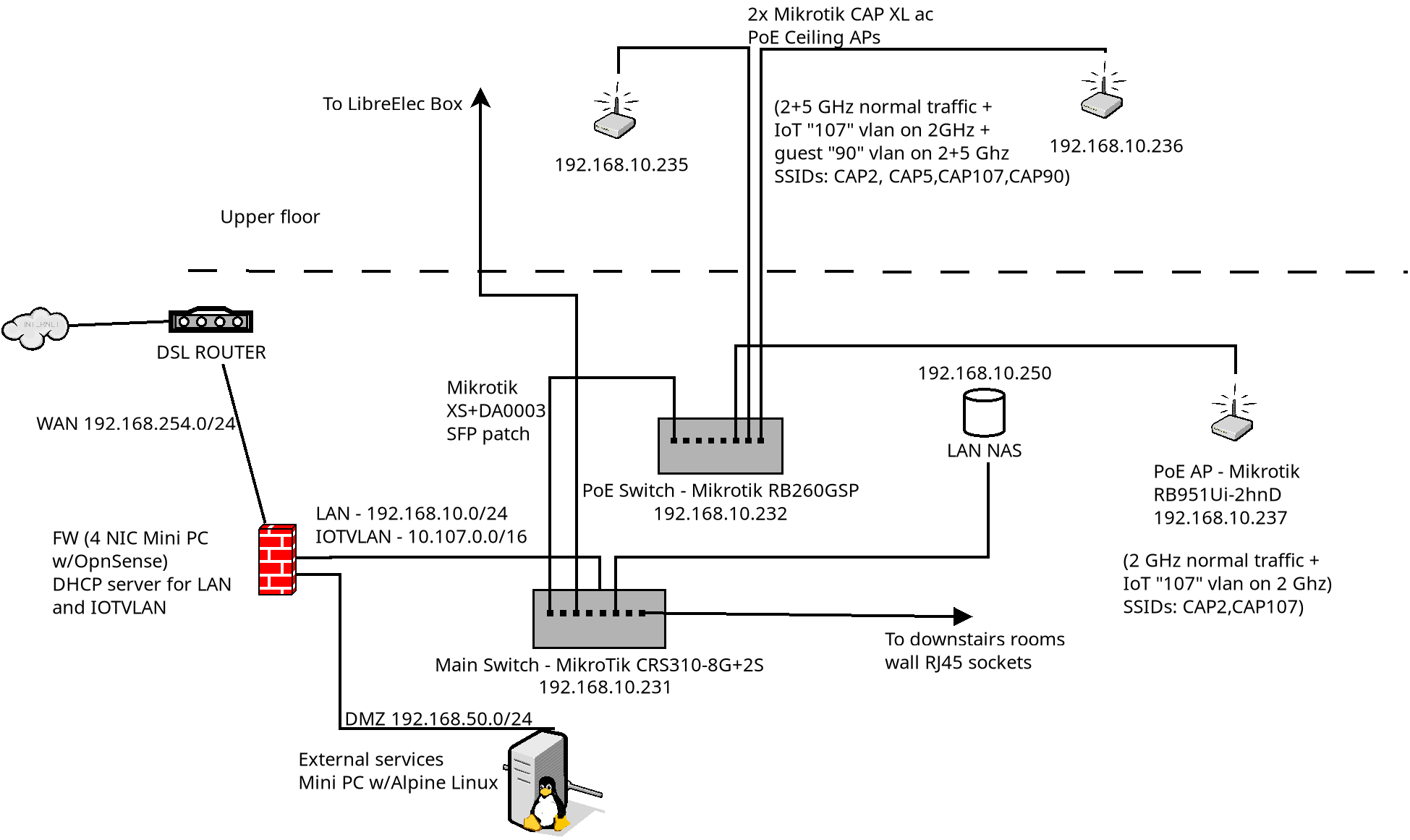
Below there is a quite horrible design of how my home network is arranged. For the moment, the Firewall isn’t connected, just treat it as a wire.
So far i have working a CRS310-8G+2S from which I feed rooms wall network sockets, a RB951ui-2hnD, then a RB260GSP which works as PoE switch and power
supply for two ceiling mounted PoE APs (CAP XL ac) located upstairs.
Home main network is 192.168.10.0/24 with the gateway (currently the DSL router) set to 192.168.10.254 and DHCP server.
homenet.png
That arrangement works beautifully, and i take the opportunity to encourage anyone in need for a AP to choose dual band ones because the 5GHz signal is really too weak to cover also a not so big house. Probably being the house quite old with thick walls and having a military airbase not far from here also doesn’t help.

A few premises to keep things as simple as possible:
I don’t need/want strong security as I live in a sparsely populated area, and strong WiFi passwords on all wireless devices would be enough.
Performance isn’t an issue: I rarely make use of all internal bandwidth, my downlink barely goes beyond 30Mb and is going to remain that low at least until they bring fiber, which has always been due in 3 months since the 1st time I asked …two years ago.

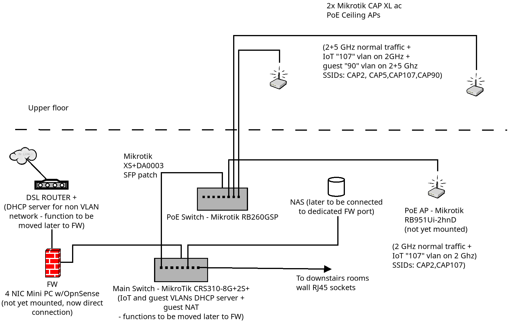
Basically,I would like to add to the above:
1- A guest VLAN (tagged “90” to allow untrusted WiFi devices to go outside, subnet 192.168.90.0/24). This is a very low priority feature to have “just in case” as usually people visiting would rather use their 4/5G phone to connect to the outside at much higher speed. I wouldn’t because i want a public IP.
2- A IoT VLAN (unsurprisingly tagged “107”, subnet 192.168.107.0/24) to connect various devices. All devices are reflashed using FOSS firmware and none of them would connect to any outside cloud service, that is, the IoT VLAN doesn’t need to access to the outside, and any access/management would be performed by a separate box (*Pi-like board, etc) working as a router/bridge.
3- A DHCP server on the CRS310 switch, which I plan to move on the firewall FW or on the small box once it’s operational.

So far, I’ve created on one of the ceiling APs: the virtual interface linked to the wlan1 (2GHz) one, a vlan bridge, a vlan dhcp client, all tagged accordingly, and on the CRS310 the corresponding vlan bridge and vlan dhcp server, but can’t seem to obtain a DHCP address. Using Torch i could see the DHCP requests from my phone being correctly tagged, but they seem confined within the access point. Then I tried with fixed addresses everywhere, again without success. I’ve been struggling for over a week with this problem and every document or video seems to add more confusion, which suggest I’m missing something very basic to proceed, hence this cry for help. Do I have to create a virtual interface for each physical one on the CRS310? This is very unclear to me as the whole mechanism of how packets travel from an interface to a bridge and back doesn’t seem clearly exposed, although in my past jobs I’ve written code to play with sockets and send/recv IP packets, encapsulate them, data conversion and alignment between different architectures etc, so I’m familiar with the concept but the documentation or the presentation wrt VLAN configuration doesn’t help to understand the mechanism.
Surely I’m missing something but have no idea what or where.
I don’t even know if that’s possible (corrections welcome!), but if a VLAN works like a virtual wire just as the one connecting physical interfaces, then I’d like to keep things as simple and transparent as possible, that is, no dedicated interfaces: every VLAN tagged packet entering whichever port on the CRS310 should be available on all others untouched, just like in a plain hub, then if something connects on the APs VLAN wireless virtual interface then can only be a IoT device and its input packets will be tagged as necessary, while output packets reaching it will be untagged. This is necessary as I don’t expect small ESP* boards and other uControllers for example to be able to connect to VLANs directly, correct me if I’m wrong. Also, I don’t plan to connect any IoT devices to any physical port, except for the above mentioned box which would work as bridge between LAN and VLAN.
Any help much appreciated, thanks!

Wont comment on a moving target. Once you have moved functionality to FW, then can be of assistance.
By the way why not get a mikrotik router to replace the DSL router and firewall…

So, let’s start from that particulat “brick”, we will oversee the general architecture later.

Follow the instructions in this post:
http://forum.mikrotik.com/t/forum-rules/173010/1
and post your configuration.

of ALL the devices you have currently set up, i.e. the CRS310 and the CAP XL.
Is the RB260GSP configured as “plain” switch or does it have a particular configuration? If the latter post that one too.

It would be a good idea to call your two identical CAP XL’s in a distinctive way, like “CAPXL#1” and “CAPXL#2”.

I’m not sure when I’ll have a stable configuration, so many things to do, also unrelated, but will try to solve anyway.

By the way why not get a mikrotik router to replace the DSL router and firewall…

When fiber will finally arrive here that will be quite likely.

of ALL the devices you have currently set up, i.e. the CRS310 and the CAP XL.
Is the RB260GSP configured as “plain” switch or does it have a particular configuration? If the latter post that one too.

Plain switch, and I’m starting to get some results: I see DHCP requests on the CRS310 but they stil don’t get a reply.
To make things easier I deleted every VLAN settings from all devices then replicated it on the RB951ui along with a DHCP server,
so that I could observe locally what I was doing and experiment without risking to brick the ceiling APs. I finally came to the conclusion that I wasn’t
seeing packets on the CRS310 because I set up the wrong way how they’re tagged, and I’m still not sure about that because the
way it’s presented on the interface is quite unclear; I find very hard to recognize which settings adds a tag and which one removes it
so I’m trying everything and probing until I come to some results. Yes, I’m aware that’s the wrongest way of doing this and for what is worth I’d
never hire myself as a network engineer :smiley:
Anyway, I started over on one of the APs and the CRS310 and now I can see DHCP requests packets tagged on the CRS310
IoT bridge. One step at a time…

It would be a good idea to call your two identical CAP XL’s in a distinctive way, like “CAPXL#1” and “CAPXL#2”.

Yes, they already are called differently and have distinct IPs, what they share are the SSIDs, although all interfaces are on different non
overlapping channels.

Well, you are doing it wrong. :open_mouth:
This way you cannot experience the satisfaction when you fire yourself. :wink: :laughing:

Well, you are doing it wrong. > :open_mouth: >

100% sure about that. Now I’m in the process of configuring the Firewall so that I’ll work on a stable configuration, but moving the LAN away from the DSL router means I’ll lose those precious ports that are now occupied, and I’m already short of them on the CRS310. Will probably have to add another switch or swap the 310 with a bigger one with similar characteristics, which I would try to avoid as it wasn’t that cheap.


This way you cannot experience the satisfaction when you fire yourself. > :wink: > > :laughing:

:laughing:

Hello again. I’ve moved a few things and configured the firewall so that the CRS310 doesn’t have to serve DHCP anymore. My network topology has changed into this:

homenet.png
I also did a few tests by first configuring a vlan tagged 107 on a virtual eth on this Debian machine, then did the same on a wlan interface of a small Orange Pi SBC that connected to the VLAN interface I had configured on one of the two CAP ac xl I have upstairs (all VLAN config is disabled on the 2nd one). Both the vlan interface here and the one on the sbc got their address from the dhcp server on the firewall and I could ping and ssh into the small sbc. This client is connected to the CRS310, so vlan packets had to travel the entire route through the RB260 and the CAP ac. Problem is that this isn’t exactly what I need, as the sbc runs a full Linux OS, therefore adding a VLAN is trivial, however I plan to use the IoT VLAN with much smaller devices too (say from ESP8266 onwards) which I’m not sure would allow packet tagging, therefore I have to set up the hardware accordingly, that is, all designated interfaces will tag incoming packets (if untagged) and untag outgoing ones, with a dedicated bridge gluing them together. The concept is so simple, yet I’ve been struggling for days trying to understand the convoluted interface and where it says “this tags the input” or “this untags the output”. Having to travel multiple hops across multiple devices also doesn’t help.
Any help really appreciated, this is consuming me a lot more than I could imagine. Thanks in advance!

Well I can only help with MIKROTIK devices.
For switches or any device acting as a switch or AP switches its quite simple.
One bridge, only one vlan identified to the bridge - aka the trusted or management vlan
The rest of the vlans are either identified on /interface bridge ports ( access port to dumb device )
or via the /interface bridge vlans depending if going to a smart device ( tagged ) or dumb device untagged.
Only the trusted/management vlan is tagged with the bridge.
The single IP address is assigned to the vlan and is the devices static IP on the trusted/managment LAN.
etc…

So ports on switch are either TRUNK ( carrying one or more vlans tagged) or access, going to dumb device.
If you require a hybrid port ( some dumbass smart devices expected trusted lan untagged and all other data vlans tagged) then that takes a bit more work.

Solved, and it was much much easier that I thought; here are some hints to help anyone having the same need.
First of all, two important points:

  • there’s no need to create a dedicated bridge on the interested access points, the default one will just work.
  • any device in the middle (see the RB310 on my picture above) if working as a simple bridge can be left as is and tagged packets will just go through.

To create a separate wireless VLAN, go to the access point WinBox interface and:

  • create a virtual wlan having as a master interface the interested physical wlan you’ll be using for that purpose.
    (In my case I created a virtual wireless lan and set wlan1 as master - On my two dual band APs wlan1 is the one working at 2.4GHz. I didn’t touch wlan2, the 5GHz interface, as I need the VLAN for small IoT devices most of which do not support 5GHz yet)

  • on the virtual interface settings set up its SSID, then on VLAN Mode: choose “use tag” and fill the VLAN ID field with the needed ID.

  • Choose the Bridge item on the left menu and on the Bridge list go to the Ports tab then add (+) the virtual interface you previously added, then click on it and fill the ID with the ID you previously set on the virtual interface.

Done. Unless I’ve left something out this should be enough. I’ve removed all my previous settings and replicated the above on all 3 APs with success, also testing with two different devices on two different APs (temporarily using different SSIDs) and the CRS310 in the middle and they would correctly see each other while remaining separated from the rest of the LAN.

Regarding the planned guest VLAN, things are almost identical, save for the need to allow guests to use the 5GHz band too where supported, and more importantly be able to reach the Internet, therefore I’ll also have to add rules to the firewall to do that.

Hope that helps!