Only one bridge (per seitch chip) can be hardware offloaded, others are handled entirely by CPU.
What you could do is configure all ports into single bridge but separate them into VLANs using switch chip configuration. It is fine to make all ports members of a VLAN access ports (=untagged), which in a sense partitions a switch while alliwing it to do it in hardware.
It might be an error of the indeed Winbox display indeed, but the manual for CRS1xx/2xx devices states the following:
Multiple switch groups
The CRS1xx/2xx series switches allow you to use multiple bridges with hardware offloading, this allows you to easily isolate multiple switch groups. This can be done by simply creating multiple bridges and enabling hardware offloading.
Given this, I’d rather look why it behaves different than expected than suspect display errors. I can imagine some broadcast traffic to bother the CPU, so it might make sense to prevent any traffic from the “transit” interfaces from reaching the CPU using switch chip rules (called ACL rules in CRS1xx/2xx case). But you have to keep in mind to allow all traffic, including broadcast frames, to reach the CPU from an interface used for management.
Once you start using the ACL rules, you may as well use a single bridge and use the ACL rules to allow ingress frames from ether1 only to egress via sfp9 and vice versa, and ingress frames from ether2 and 3 to egress via SFP10 and vice versa.
What I don’t like about the setup is that STP is permitted on the bridge - depending on how paranoid the ISP admins are, you may or may not break their own spanning tree topology by making your CRS a root bridge. So I’d rather disable it on the bridge(s) completely.
# sep/14/2022 20:37:18 by RouterOS 7.5
# software id = SZII-F003
#
# model = CRS112-8P-4S
# serial number =
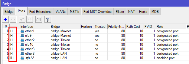
/interface bridge add name=bridge-LAN
/interface bridge add name=bridge-Maxnet
/interface bridge add name=bridge-Triolan
/interface ethernet set [ find default-name=ether1 ] comment="Maxnet -> 4011 port 1" poe-out=off
/interface ethernet set [ find default-name=ether2 ] comment="Triolan -> 4011 port 2" poe-out=off
/interface ethernet set [ find default-name=ether3 ] comment="Triolan -> 4011 port 3 (IPTV)" poe-out=off
/interface ethernet set [ find default-name=ether8 ] comment="-> 4011 port 4"
/interface ethernet set [ find default-name=sfp9 ] comment=Maxnet
/interface ethernet set [ find default-name=sfp10 ] comment=Triolan
/interface list add name=LAN
/interface list add name=WAN
/interface bridge port add bridge=bridge-Maxnet ingress-filtering=no interface=ether1 trusted=yes
/interface bridge port add bridge=bridge-Maxnet ingress-filtering=no interface=sfp9 trusted=yes
/interface bridge port add bridge=bridge-Triolan ingress-filtering=no interface=ether2
/interface bridge port add bridge=bridge-Triolan ingress-filtering=no interface=sfp10
/interface bridge port add bridge=bridge-Triolan ingress-filtering=no interface=ether3
/interface bridge port add bridge=bridge-LAN interface=ether8
/interface bridge port add bridge=bridge-LAN interface=sfp12
/ip firewall connection tracking set icmp-timeout=30s tcp-close-wait-timeout=1m tcp-established-timeout=1h tcp-fin-wait-timeout=2m tcp-last-ack-timeout=30s tcp-syn-received-timeout=1m tcp-syn-sent-timeout=2m tcp-time-wait-timeout=2m udp-stream-timeout=2m udp-timeout=30s
/ip neighbor discovery-settings set discover-interface-list=none
/ip settings set tcp-syncookies=yes
/ipv6 settings set disable-ipv6=yes
/interface list member add interface=bridge-Maxnet list=WAN
/interface list member add interface=bridge-Triolan list=WAN
/interface list member add interface=bridge-LAN list=LAN
/ip address add address=172.22.0.231/24 interface=bridge-LAN network=172.22.0.0
/ip dns set cache-max-ttl=5m servers=172.22.0.254
/ip firewall raw add action=accept chain=prerouting comment="DHCP request Maxnet" in-interface=bridge-Maxnet port=67,68 protocol=udp
/ip firewall raw add action=drop chain=prerouting comment="Drop all from WAN" in-interface-list=WAN
/ip firewall service-port set tftp disabled=yes
/ip firewall service-port set irc disabled=yes
/ip firewall service-port set h323 disabled=yes
/ip firewall service-port set sip disabled=yes
/ip firewall service-port set pptp disabled=yes
/ip firewall service-port set dccp disabled=yes
/ip firewall service-port set sctp disabled=yes
/ip route add check-gateway=arp disabled=no dst-address=0.0.0.0/0 gateway=172.22.0.254
/ip service set telnet address=172.16.0.0/12
/ip service set ftp address=172.16.0.0/12
/ip service set www disabled=yes
/ip service set ssh address=172.16.0.0/12
/ip service set api disabled=yes
/ip service set api-ssl disabled=yes
/ip ssh set strong-crypto=yes
/snmp set contact=Admin enabled=yes location="MO IT" trap-version=2
/system clock set time-zone-name=Europe/Kiev
/system identity set name=rt-mo-optic
/system ntp client set enabled=yes
/system ntp client servers add address=172.22.0.254
/system routerboard settings set auto-upgrade=yes
/tool bandwidth-server set enabled=no
/tool mac-server set allowed-interface-list=LAN
/tool mac-server mac-winbox set allowed-interface-list=LAN
Switching bridges from mode “RSTP” to mode “none” only worsened the situation: the CPU utilization increased to 95-100%.
Do I understand correctly, that I need to remove all current bridges, and then create a new bridge and add all necessary ports to it. And then use this instruction
That’s strange if the partitioning of the switch works; if it doesn’t, I’m afraid the ISP admins are scratching their heads what it was as you may have interconnected their networks together.
If the switch chip partitioning by configuring multiple bridges fails, then yes, this other approach may be the solution. Except that this instruction describes a more usual case where the three groups (communities) share the uplink ports (traffic between any uplink port and any downlink port is permitted, and so is traffic between any two downlink ports in the same group, only traffic between downlink ports in different groups is forbidden), so you have to adjust the isolation profiles to match your needs, i.e. you would put ether1 and sfp9 into community 0 (isolation-leakage-profile-override=2) and ether2, ether3, and sfp10 into community 1 (isolation-leakage-profile-override=3). However, the example does not say what happens to other ports and what happens to the CPU-facing port when you set these, so expect some sparks until you grasp it. And the goal remains to prevent traffic from each group from leaking elsewhere, not only to the other group but also to the CPU, and at the same time keep the device manageable through another port. So attaching a management subnet to an Ethernet interface that is not a member port of any bridge is the first thing to do before you even start redoing the rest.
If I were you, I would first check whether the traffic indeed leaks between the currently configured bridges by placing the switch on the table and connecting two PCs to it to see whether they can talk to each other when connected to two ports in the same bridge (they should) and to two ports on different bridges (they should not). Of course with copper ports added to each bridge unless you have copper SFPs. And only if it turns out that the “dual bridge” approach indeed leaks the traffic between the bridges, I’d move to the other approach.
Note 1: I strongly recommend, that you have a console cable for recovery at hand, when experimenting with setting up switch chips.
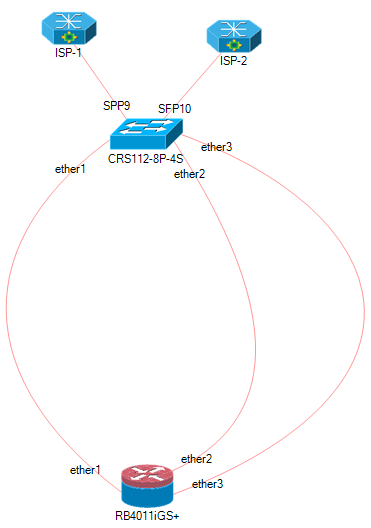
Current (initial) configuration: 3 bridges. The first is provider 1 (2 ports), the second is provider 2 (3 ports), the third is the local network (2 ports).
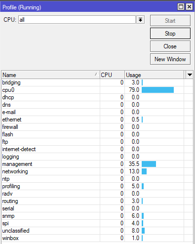
The problem with the initial configuration is a high CPU load with constant traffic at a speed of 50+ Mbps.
What has been tested:
Complete reset of the configuration, reconfiguring the current configuration with three bridges. All operations were performed from the command line.
Full configuration reset, ROS 7.5 installation via Netinstall , configuration setting in the two-bridge option (only bridges for providers). Configuration was done through the console port.
Complete configuration reset, configuration setting in the single bridge option. Used the division of traffic between ports using a switching chip. Configuration was done through the console port.
The result of all three tests is the same - no decrease in the load on the central processor was noticed.
Note 2: I would like to note that all options were configured as follows: disconnecting optical cables from providers, complete configuration reset, configuration, reboot, connecting cables from providers, reboot.
CPU load monitoring started 15 minutes after the last reboot.
# Create new bridge

/interface bridge add name=bridge1 protocol-mode=none

/interface bridge port add bridge=bridge1 interface=sfp9 hw=yes
/interface bridge port add bridge=bridge1 interface=ether1 hw=yes
/interface bridge port add bridge=bridge1 interface=sfp10 hw=yes
/interface bridge port add bridge=bridge1 interface=ether2 hw=yes
/interface bridge port add bridge=bridge1 interface=ether3 hw=yes

# Maxnet
/interface ethernet switch port
set sfp9 isolation-leakage-profile-override=2
set ether1 isolation-leakage-profile-override=2
/

/interface ethernet switch port-isolation
add port-profile=2 ports=sfp9,ether1 type=dst
/

# Triolan
/interface ethernet switch port
set sfp10 isolation-leakage-profile-override=3
set ether2 isolation-leakage-profile-override=3
set ether3 isolation-leakage-profile-override=3
/

/interface ethernet switch port-isolation
add port-profile=3 ports=sfp10,ether2,ether3 type=dst
/
Note 3: Downgrading via Netinstall to firmware version 6.49.6 Stable has not been tested.
Note 4: after disconnecting the cables from the providers and completely resetting the settings, there is a constant CPU load of 10%. In this case, only the cable between the CRS112-8P-4S and the laptop was connected. Observation was made using Winbox.
What happens if you run /tool sniffer quick interface=bridgeX (where bridgeX is one of the ISP bridges)? I mean, either there’s a bug or the CPU load is caused by too many packets reaching the CPU as I’ve suggested initially, and the sniffer should show you how many such packets there actually are.
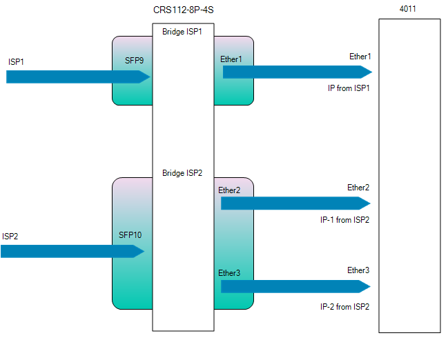
Two providers. The first - provides one IP address, the second - two. Two addresses - for two tasks. Therefore, two interfaces for 4011 from the second provider are connected.
As for the rules of the firewall. I do not like attempts to explore the MAC address or conduct another incomprehensible and unknown activity to me. Therefore, I wanted to close the incoming chain.
The third bridge is for connecting from the local network. For the purpose of monitoring and tuning. This bridge also has two interfaces, because sometimes equipment is replaced in the local network and I need to be able to connect via optics or twisted pair.
I understand that all these settings can be done differently, using VLANs. And then only one cable is required between the switch and the router. To be honest - it seemed to me that a scheme with several bridges would be easier for the switch to process. And the load on the switch's CPU will be lower.
In addition, I tried to configure a variant without any firewall rules, on a single bridge, using a switching chip. The result did not please me. It's possible that I'm setting something up wrong.
Is possble to have more than one IP on same interface…
I have 4096 IPs from my upstream, but I do not need 4096 cables…
If you want use 8P as media converter, use it as media converter,
any operation than simply switching (is a switch…) cause high CPU load…
For use it as double media converter, and keeping sfp12 and ether8 (and also the other ports not mentioned) for other bridges, management, or other uses,
reset all configuration without default, when you do /export must not export any relevant.
No IP firewall reqired, because the device do not have any IP (except what is coming on ether8 from RB4011),
until you do not connect other internet sources.
Bingo. If you want line-rate switching, you cannot do anything to the packets that forces them to cross the CPU. That includes firewalling, but it isn’t limited to it. The packets have to stay on the switch chip.
This series has ACL rules that work purely at the switch chip level, but they’re less powerful than RouterOS’s full firewall.
The main idea is clear. Although these port isolation rules do not apply to this switch model. I described above, in paragraph 3, the rules, that I used to work on the switch chip. In this case, no firewall rules were used. However, the load on the CPU was still high. I will try, in the coming days, to once again experiment with working through the switching chip and post more complete results.
On a single cable, you still have the bandwidth of a single cable (for all of those 4096 IP addresses together). So yes, where a single ISP fiber provides two IP addresses, maybe they could be attached to the same interface at the 4011, but I can see nothing strange on using another physical interface on the 4011 for the second ISP. That router can handle more than 1 Gbit/s per direction.
The whole idea @BrateloSlava wants to implement is correct, the only issue is where the load of the CRS CPU comes from.
@BrateloSlava, instead of running /tool sniffer, it is probably more useful to add the following bridge filter rules: interface bridge filter add chain=input in-bridge=bridge-name dst-mac-address=ff:ff:ff:ff:ff:ff/ff:ff:ff:ff:ff:ff action=passthrough
interface bridge filter add chain=input in-bridge=bridge-name action=passthrough
and then run /interface bridge filter print stats interval=10s
We are interested in the two subsequent outputs, to see how many packets and bytes got caught by each of the two rules during 10 seconds.
The idea is that only frames that reach the CPU port of the switch chip will get caught by one of these rules, so you'll see the amount of that traffic, and you'll also see how much of it is broadcast (presumably all of it) and how much is unicast (to the device's own MAC address, presumably none). Traffic between the SFP and the copper port will not reach the CPU so it won't get caught by these rules.
Of course, these rules will increase the CPU load even more, but it's necessary to do this test to understand whether the root cause of the high CPU load is too much broadcast traffic or a bug in 7.x. But to keep the CPU load as low as possible, I'd recommend to use the rules for just one bridge at a time.
There’s something special about this switch that prevents forwarding override from functioning? it’s not mentioned anywhere. Please provide a link to where you got this “information” from.
As an addition to the rules posted above you’ll have to override all the other ports too because otherwise they will forward traffic by default to all the other ports, including to those that you’ve set override rules (just that it’s one way now because of that).