Temporary Rescue Bridge During VLAN Setup
Hi everyone,
I recently configured a CRS305 and wanted to enable VLAN filtering without risking a lockout during the migration.
The usual advice is:
-
Use Safe Mode
-
Keep serial access available
-
Be prepared to reset the device
All of that is valid advice.
However, I found a simple approach that made the entire migration much less stressful and wanted to share it in case it helps other beginners.
Example VLAN Design
The exact VLANs are not important. For this example, assume a simple setup like:
VLAN 10  MGMT
VLAN 20  TRUSTED
VLAN 30  SERVER
VLAN 40  STORAGE
The goal is to enable VLAN filtering and move management into the MGMT VLAN without losing access to the switch.
The Problem
Most tutorials assume that you modify the bridge that you are currently using for management.
That means every change is potentially dangerous:
-
Wrong VLAN table
-
Wrong PVID
-
Wrong management interface
-
Wrong tagging configuration
Any of these mistakes can lock you out.
The result is often a stressful workflow where every click feels risky.
The Idea
Before touching the production bridge, create a completely separate management path.
Instead of relying on the same bridge that is being modified, temporarily move one physical port into its own dedicated rescue bridge.
The rescue bridge is not intended to be permanent.
Its purpose is simply:
If I break something while configuring VLANs, I still have a way back in.
Hardware Considerations
In my case, the CRS305 only has a single RJ45 port.
The remaining ports are SFP+.
I wanted two completely independent paths:
-
A rescue connection.
-
The future production/trunk connection.
To achieve this, I used a TP-Link TL-SM331T SFP RJ45 module in sfp-sfpplus1.
The physical setup looked like this:
Workstation
 ├─ Ethernet Adapter #1
 │    └─ ether1 (rescue connection)
 │
 └─ Ethernet Adapter #2
      └─ RJ45
           └─ TP-Link TL-SM331T
                └─ sfp-sfpplus1 (future trunk)
This allowed me to work on the future trunk while maintaining a completely separate management path.
Step 1: Create a Rescue Bridge
Create a second bridge:
/interface bridge
add name=rescue-bridge comment="Temporary rescue bridge"
Step 2: Move One Port
Remove one physical port from the production bridge and assign it to the rescue bridge.
The resulting topology becomes:
Before:

bridge
 ├─ ether1
 ├─ sfp-sfpplus1
 ├─ sfp-sfpplus2
 ├─ sfp-sfpplus3
 └─ sfp-sfpplus4

After:

bridge
 ├─ sfp-sfpplus1
 ├─ sfp-sfpplus2
 ├─ sfp-sfpplus3
 └─ sfp-sfpplus4

rescue-bridge
 └─ ether1
Step 3: Assign a Temporary Management Address
Assign a dedicated management address to the rescue bridge.
The specific subnet is not important.
For example:
/ip address
add address=192.168.88.1/24 interface=rescue-bridge
Configure your workstation with a matching address and verify that you can access the switch through the rescue bridge before continuing.
This step is critical.
Do not proceed until you have confirmed that the rescue bridge works.
Step 4: Stop Touching the Rescue Bridge
Once the rescue bridge is operational:
Leave it alone.
Do not add VLANs to it.
Do not move interfaces around.
Do not optimize it.
Treat it as an emergency access path.
All further VLAN work should happen exclusively on the production bridge.
This means that even if you completely break:
-
VLAN filtering
-
VLAN membership
-
PVIDs
-
Tagged management
-
Management VLANs
you still have a working path back into the device.
Step 5: Perform the VLAN Migration
At this point you can safely:
-
Enable VLAN filtering
-
Build the VLAN table
-
Configure PVIDs
-
Configure trunk ports
-
Configure access ports
without risking a complete lockout.
In my setup, tagged management only started working reliably after I moved the management IP from the bridge to a dedicated management VLAN interface.
For example:
/interface vlan
add name=vlan-mgmt interface=bridge vlan-id=10
Then move the management IP to that VLAN interface.
Once I did this, tagged management immediately started working as expected.
Step 6: Verify the New Management Path
Before removing the rescue bridge, verify that:
-
Tagged management works through the trunk.
-
The management VLAN is reachable.
-
The Web UI works.
-
WinBox works (if used).
-
Ping works.
Do not skip this step.
The rescue bridge should remain available until the new management path has been fully tested.
Step 7: Reintegrate the Rescue Port
Once the new management path is verified:
-
Remove the temporary rescue bridge.
-
Return the rescue port to the production bridge.
-
Configure it according to your final design.
For example, it might become:
-
an untagged management port
-
a normal access port
-
a spare troubleshooting port
At this point the rescue bridge has served its purpose and can be removed.
Why This Worked So Well
The rescue bridge did not solve the VLAN problem itself.
It solved the fear of making mistakes while solving the VLAN problem and allowed me to make mistakes safely while solving the VLAN problem.
Before creating the rescue bridge, every change felt risky.
After creating the rescue bridge, mistakes became cheap.
That changed the entire troubleshooting process.
Instead of thinking:
“If this goes wrong, I may need to factory-reset the switch.”
I could think:
“Let’s see what happens. If I break something, I still have a way back in.”
The result was a much calmer and more methodical migration.
Conclusion
This is not a replacement for:
-
Safe Mode
-
Serial access
-
Configuration backups
However, for beginners learning RouterOS VLANs on CRS3xx switches, a temporary rescue bridge provides a simple safety net and makes experimentation significantly less stressful.
Before making a risky networking change, ask yourself a simple question:
What is my lifeline?
If you do not have an answer yet, you may not be ready to make the change.
Addendum: Don’t Ignore “mlag not connected”
While performing this migration, I repeatedly encountered a comment in RouterOS similar to:
mlag not connected
My initial assumption was that this was unrelated because I was not intentionally configuring MLAG.
That assumption turned out to be wrong.
I encountered this behaviour on both a CRS310 and later on a CRS305.
In both cases, the affected bridge port showed:
mlag not connected
and did not behave as expected.
The interesting part is that in both cases I was able to resolve the issue with the same procedure:
-
Remove the affected port from the bridge.
-
Re-add the port to the bridge from the RouterOS console.
-
Verify that the bridge port has been recreated correctly.
For example:
/interface bridge port remove <port-id>

/interface bridge port add \
    bridge=bridge \
    interface=<interface-name>
After recreating the bridge port, the issue disappeared on both devices.
I do not know whether this indicates a RouterOS bug, a stale bridge-port state, an MLAG-related configuration artifact, or something else entirely.
However, based on my experience, I would recommend the following:
If you see “mlag not connected” on a bridge port and the port is not behaving as expected, do not automatically dismiss it as a cosmetic warning.
Instead, inspect the bridge-port configuration and consider removing and re-adding the affected port.
That simple procedure resolved the problem for me on both the CRS310 and the CRS305.

 . Sharing knowledge is good, but in this case the specific thread has recently been referenced in almost every new thread about VLAN, and before that thread exists, the suggestion to take a port out for emergency access before setting up VLAN was also a very common suggestion.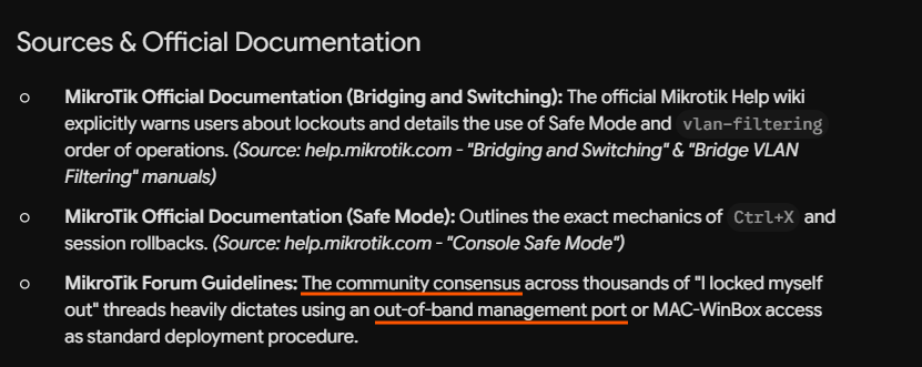
 .
.


 The guide was created by