I can do the attached image in the old format manually placing vlans under each eth port and using 4 bridges and manually connecting each to bridge exactly as per image.
Every time I try program the above in new bridge vlan format so I can simplify program I fail badly.
I either end up with vlan 3 and 145 on ports I don’t want or I can connect vlan 3 tagged in to main bridge
Can anyone shed some light how to do it on new format with minimal bridges
I said that is the old way I can’t actually even draw it the new way because I can’t even establish how many bridges I need. I am thinking two but not even sure on that
Everytime I try with one it fails because vlan 3 and 145 comes back out eth4. On a single bridge you seem to be only able to have all the tagged ports come out to a port there seems to be no way to remove some of them for a certain ethernet port.
On a single bridge vlan3 and 145 are on the tagged list and so when I select eth4 they come out there as well. I assume 10, 22 and 24 also end up at ethernet 1 but in that instance it isn’t fatal as the connection has vlan filters.
As I said I have tried this numerous ways but I am obviously missing something basic because I can not construct that arrangement.
Make your best effort to configure and then post your config here so we can see what you’re getting stuck on. I guarantee it can be done. VLANs on MT (new method) definitely take a bit for your mind to get comfortable with.
Just in case you don’t know, to export and post config:
From CLI - export hide-sensitive file=NameOfConfig. Then download the file, open in notepad or whatever, remove your serial number and paste the rest in a message using code formatting option.
Your diagram is actually quite helpful to see which ports need to be tagged or untagged on the single bridge.
I will assume that you take the time to read the reference above.
The next step, after reading the above, is for you to at least show us what you think is correct, or in the right direction, even if it does not work and we can go from there, explaining in some detail how to achieve success and why.
/export file=anynameyouwish ( minus router serial number, any public WANIP info, keys )
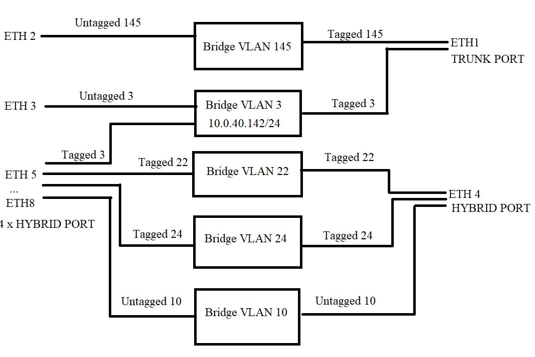
What exactly is incorrect, my suggestion implements the diagram from the OP which has
ether1: 3t,145t
ether2: 145u
ether3: 3u
ether4: 10u,22t,24t
ether5: 10u,3t,22t,24t
ether6: 10u,3t,22t,24t
ether7: 10u,3t,22t,24t
ether8: 10u,3t,22t,24t
plus VLAN3 with IP 10.0.40.142/24
Probably I have incorrectly determined the nature of the diagram. It looked to me like ether5 was a trunk port. add bridge=bridge frame-types=admit-only-vlan-tagged ingress-filtering=yes interface=ether5 comment="trunk port
However, you may have read it correct in that the left hand menu possible says ether 5 to ether 8, as opposed to eth5, and eth8 separately.
It would help if the OP detailed what device was at the other end of each physical port.
TDW thank you very much that appears to be correct and I will check it in situ tomorrow.
anav there was nothing to export the switch is blank empty that is all it does it’s a standard layout for a ubiquiti dream machine.
ether 1 is trunk tag in Vlan 145 internet Vlan 3 management
ether 2 is DM internet out (for a reason only know to ubiquiti they hate trunk input)
ether 3 is management out to UPS monitoring
ether 4 is Dream machine LANS coming in to be distributed
ether 4 to 8 are the APS with 10 PVID & 20,22 VIDS
Anyhow thanks to all I learnt a lot for complex layouts with new format.