Setting up an RB5009 to upgrade a home office was pretty straight forward until I moved on to use vlans to separate guests IOT devices, personal PCs, and business PCs. Wrapping my head around the Mikrotik way of setting up the vlans has been interesting. I have found three great posts on this forum:
I think best visually so I undertook to create a visual representation of Mikrotik vlans similar to what @sindy so clearly laid out. The discussion of this occurred deep into the comments on his post. It was suggested that I should shift my work to a new topic. The following is a copy of my last reply to that conversation. If interested my progression to this, however, you may want to start at RouterOS bridge mysteries explained - #95 by DocPneumo
This is a work in progress for me so recommendations, corrections, and refinements are welcome
Convention:
These commands assume starting from a clean slate. ie no defaults. keep-users can be helpful, though. Starting from the default state ( /system reset-configuration ) would probably be safer as it leaves the default Mikrotik firewall in place. See the @Buckeye comment below.
ingress-filtering defaults to yes. This rejects frames tagged with vlan-id
not associated with a vlan sub-interface on the switch facing router interface.
Anonymous sub-ports are created on the router-facing switch port
In that case most ports have already been added to the bridge, but the vlan-aware has not been established. But the bridge already has ip address 192.168.88.1/24
[admin@MikroTik] > export
# 2025-09-19 00:39:49 by RouterOS 7.19.4
# software id = TRCJ-GM9Q
#
# model = RB760iGS
# serial number = *removed*
/interface bridge
add admin-mac=DC:2C:6E:7B:10:F2 auto-mac=no comment=defconf name=bridge
/interface list
add comment=defconf name=WAN
add comment=defconf name=LAN
/interface wireless security-profiles
set [ find default=yes ] supplicant-identity=MikroTik
/ip pool
add name=default-dhcp ranges=192.168.88.10-192.168.88.254
/ip dhcp-server
add address-pool=default-dhcp interface=bridge name=defconf
/disk settings
set auto-media-interface=bridge auto-media-sharing=yes auto-smb-sharing=yes
/interface bridge port
add bridge=bridge comment=defconf interface=ether2
add bridge=bridge comment=defconf interface=ether3
add bridge=bridge comment=defconf interface=ether4
add bridge=bridge comment=defconf interface=ether5
add bridge=bridge comment=defconf interface=sfp1
/ip neighbor discovery-settings
set discover-interface-list=LAN
/interface list member
add comment=defconf interface=bridge list=LAN
add comment=defconf interface=ether1 list=WAN
/ip address
add address=192.168.88.1/24 comment=defconf interface=bridge network=192.168.88.0
/ip dhcp-client
add comment=defconf interface=ether1
/ip dhcp-server network
add address=192.168.88.0/24 comment=defconf dns-server=192.168.88.1 gateway=192.168.88.1
/ip dns
set allow-remote-requests=yes
/ip dns static
add address=192.168.88.1 comment=defconf name=router.lan type=A
/ip firewall filter
add action=accept chain=input comment="defconf: accept established,related,untracked" connection-state=established,related,untracked
add action=drop chain=input comment="defconf: drop invalid" connection-state=invalid
add action=accept chain=input comment="defconf: accept ICMP" protocol=icmp
add action=accept chain=input comment="defconf: accept to local loopback (for CAPsMAN)" dst-address=127.0.0.1
add action=drop chain=input comment="defconf: drop all not coming from LAN" in-interface-list=!LAN
add action=accept chain=forward comment="defconf: accept in ipsec policy" ipsec-policy=in,ipsec
add action=accept chain=forward comment="defconf: accept out ipsec policy" ipsec-policy=out,ipsec
add action=fasttrack-connection chain=forward comment="defconf: fasttrack" connection-state=established,related hw-offload=yes
add action=accept chain=forward comment="defconf: accept established,related, untracked" connection-state=established,related,untracked
add action=drop chain=forward comment="defconf: drop invalid" connection-state=invalid
add action=drop chain=forward comment="defconf: drop all from WAN not DSTNATed" connection-nat-state=!dstnat connection-state=new in-interface-list=WAN
/ip firewall nat
add action=masquerade chain=srcnat comment="defconf: masquerade" ipsec-policy=out,none out-interface-list=WAN
/ipv6 firewall address-list
add address=::/128 comment="defconf: unspecified address" list=bad_ipv6
add address=::1/128 comment="defconf: lo" list=bad_ipv6
add address=fec0::/10 comment="defconf: site-local" list=bad_ipv6
add address=::ffff:0.0.0.0/96 comment="defconf: ipv4-mapped" list=bad_ipv6
add address=::/96 comment="defconf: ipv4 compat" list=bad_ipv6
add address=100::/64 comment="defconf: discard only " list=bad_ipv6
add address=2001:db8::/32 comment="defconf: documentation" list=bad_ipv6
add address=2001:10::/28 comment="defconf: ORCHID" list=bad_ipv6
add address=3ffe::/16 comment="defconf: 6bone" list=bad_ipv6
/ipv6 firewall filter
add action=accept chain=input comment="defconf: accept established,related,untracked" connection-state=established,related,untracked
add action=drop chain=input comment="defconf: drop invalid" connection-state=invalid
add action=accept chain=input comment="defconf: accept ICMPv6" protocol=icmpv6
add action=accept chain=input comment="defconf: accept UDP traceroute" dst-port=33434-33534 protocol=udp
add action=accept chain=input comment="defconf: accept DHCPv6-Client prefix delegation." dst-port=546 protocol=udp src-address=fe80::/10
add action=accept chain=input comment="defconf: accept IKE" dst-port=500,4500 protocol=udp
add action=accept chain=input comment="defconf: accept ipsec AH" protocol=ipsec-ah
add action=accept chain=input comment="defconf: accept ipsec ESP" protocol=ipsec-esp
add action=accept chain=input comment="defconf: accept all that matches ipsec policy" ipsec-policy=in,ipsec
add action=drop chain=input comment="defconf: drop everything else not coming from LAN" in-interface-list=!LAN
add action=fasttrack-connection chain=forward comment="defconf: fasttrack6" connection-state=established,related
add action=accept chain=forward comment="defconf: accept established,related,untracked" connection-state=established,related,untracked
add action=drop chain=forward comment="defconf: drop invalid" connection-state=invalid
add action=drop chain=forward comment="defconf: drop packets with bad src ipv6" src-address-list=bad_ipv6
add action=drop chain=forward comment="defconf: drop packets with bad dst ipv6" dst-address-list=bad_ipv6
add action=drop chain=forward comment="defconf: rfc4890 drop hop-limit=1" hop-limit=equal:1 protocol=icmpv6
add action=accept chain=forward comment="defconf: accept ICMPv6" protocol=icmpv6
add action=accept chain=forward comment="defconf: accept HIP" protocol=139
add action=accept chain=forward comment="defconf: accept IKE" dst-port=500,4500 protocol=udp
add action=accept chain=forward comment="defconf: accept ipsec AH" protocol=ipsec-ah
add action=accept chain=forward comment="defconf: accept ipsec ESP" protocol=ipsec-esp
add action=accept chain=forward comment="defconf: accept all that matches ipsec policy" ipsec-policy=in,ipsec
add action=drop chain=forward comment="defconf: drop everything else not coming from LAN" in-interface-list=!LAN
/system clock
set time-zone-name=America/New_York
/tool mac-server
set allowed-interface-list=LAN
/tool mac-server mac-winbox
set allowed-interface-list=LAN
[admin@MikroTik] >
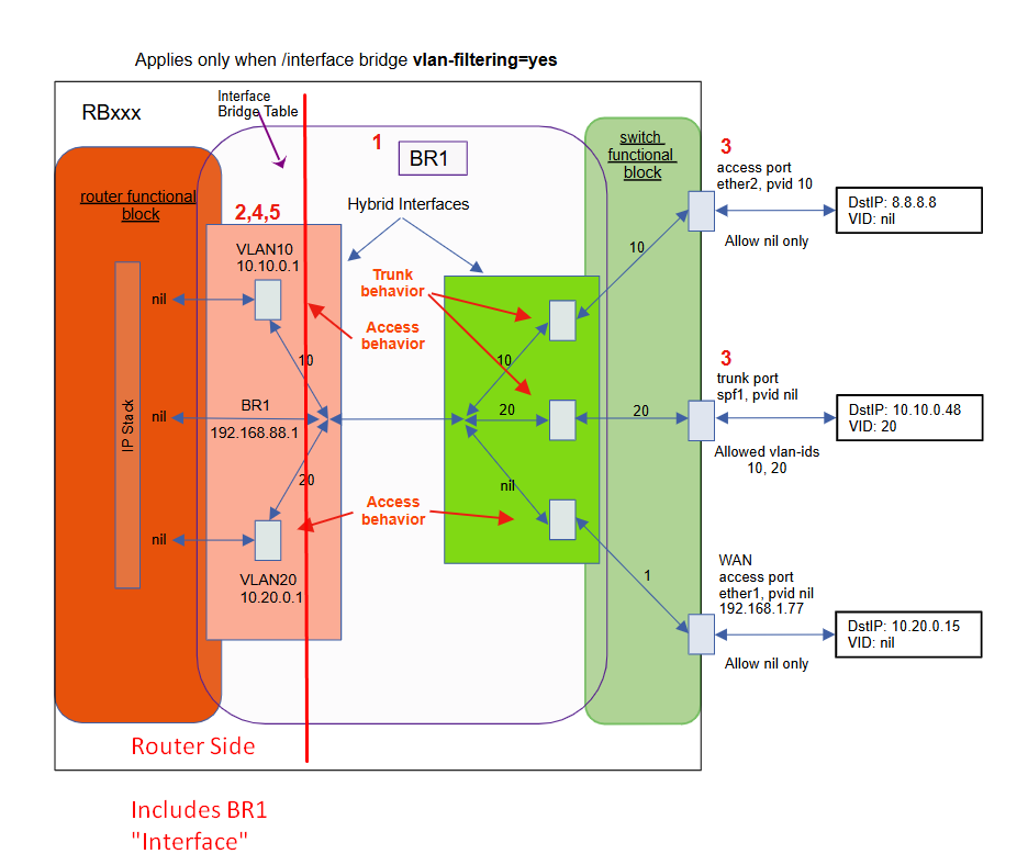
I'm sorry if this is obvious or basic, but could you please explain the visual components -- that is, what do each of the colors (pink, orange, red, light green, green, white), the gray rectangular boxes, the red lines, the blue lines, the curved corner rectangles, and the square corner rectangles.
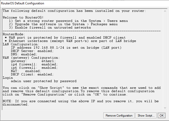
I guess this depends a lot on who the target audience is, but if this is aimed at new Mikrotik users, I think the "starting point" should be the defconf. That does a lot of the grunt work of setting up a basic usable router, with a dhcp client on either1 (WAN), nat masquerade, firewall, ntp time source, bridge (with vlan-filtering off) with LAN ip address 192.168.88.1/24, dhcp server for LAN, dns forwarder, e.g. a config very similar to a "consumer home router".
Starting from a known safe working state will help eliminate a lot of other questions unrelated to vlan configuration on the bridge.
In my opinion all the turtorials on the internet that explain "how to setup your Mikrotik router for home use - from scratch" are dangerous. Most of them are doing a demo with their "demo" router getting it ip address from their home router that already has a firewall. Without that protection, many of these routers may get compromised while being setup. Not all ISPs provide port isolation from other subscribers on the same segment. And if you reset your router without a default, and you export, you will see nothing, because it only shows things that are different from an empty config. But if you do an /export verbose you will see there is a lot there. And you will see this:
/tool mac-server
set allowed-interface-list=all
/tool mac-server mac-winbox
set allowed-interface-list=all
/tool mac-server ping
set enabled=yes
The point is, it is not safe to connect to the internet with an empty config, unless you can be assured there is something protecting you from other devices on the "WAN" connection.
I agree. Especially about needing to understand what a switch and a router do when using IEEE 802.1Q vlans.
NOTE WELL: as of 2025-09-20, this is just typed in without any testing, so there may be some mistakes. I will need to set this up to verify it works as I predict. The blurred out parts can be revealed by clicking on them.
One thing I think would be useful from a tutorial standpoint would be demonstration with two microtik devices, one configured as a router, and the other as a switch (all ports in bridge), with packet captures of what is traversing the link between the router ether2 and the switch ether2. And a raspberry pi with eth0 configured as a "hybrid port" connected to ether3 on the switch device, e.g. eth0 and eth0.10, both with dhcp clients enabled.
First with default config, with no vlans and vlan-filtering off. bridge with ip address 192.168.88.1/24 and dhcp server for 192.168.88.0/24 network. The switch device should have vlan-filtering off. In this configuration, the raspberry pi should get an ip address on its eth0 interface from the router's dhcp server.
Adding vlan 10 interface to router under the bridge, e.g. br1.10, with ip address 192.168.10.1/24 and dhcp server for the 192.168.10.0/24 network. At this point the raspberry pi should get an addres from the 192.168.10.0/24 network, and should be able to ping the router, and the router should be able to ping it. The traffic on the link between the router and the switch will have tagged traffic for 192.168.10.0/24 and untagged traffic for 192.168.88.0/24.
Turn on vlan-filtering on the switch device. Now traffice on 192.168.88.0/24 will be working on the switch utilizing the default vlan 1, because all ports will be configured as access ports for vlan 1 (pvid=1). But traffic on 192.168.10.0/24 will be blocked at the switch (bridge) due to ingress-filtering.
On the switch, configure the two ports in use to be tagged members of vlan 10. /interface/bridge/vlan add bridge-bridge tagged=bridge,ether2,ether3
At this point the raspberry pi's eth0.10 interface should start working again.
now move raspberry pi from ether3 to ether4. (before you do, predict what will happen, to test your understanding). the raspberry pi eth0.10 interface will loose connectivity, because switch:ether4 is not a tagged member of vlan 10
On the switch, turn off vlan-aware (/interface/bridge set vlan-filtering=no) Do you notice any change? The raspberry pi on switch:ether4 now has access to tagged traffic again, this is because when vlan-filtering=off the switch (bridge) is vlan transparent (it is not treating frames with ethertype set to 0x8100 any differently.
Move the raspberry pi back to switch:ether3. Verify that pings to both 192.168.88.1 and 192.168.10.1 work.
On the switch turn vlan-aware mode back on. /interface/bridge/set bridge vlan-filtering=yes Verify that pings to both 192.168.88.1 and 192.168.10.1 work. Note that it behaves the same (because vlan 10 traffic is tagged on ether2 bridge-port trunk (hybrid) as well as bridge-port ether3 (also configured as hybrid).
Connect PC with 'obtain ip address automatically" to ether4 on switch. Was it able to obtain an ip address? Can you explain why?
Change the pvid of switch:ether4 to 10. /interface/bridge/port set interface=ether4 pvid=10 Predict what will happen. Does PC still have connection to 192.168.88.1? What about 192.168.10.1 You will loose access to both because the PC is now connected to vlan 10 in the 192.168.10.0/24 network, the PC still has an ip address in the 192.168.88.0/24 network, because the PC didn't loose link status, it never intiated a new dhcp discovery. To get it to work, you can either user cmd ipconfig/release followed by ipconfig /renew or you can unplug wait a few seconds and the replug the pc into ether4. The PC should then get an ip in the 192.168.10.0/24 network.
After the PC has an address in 192.168.10.0/24, is it able to ping 192.168.10.1? What about 192.168.88.1? What about the ip addresses that the raspberry pi has on eth0.10 (in 192.168.10.0/24) and eth0 (in 192.168.88.0/24) ? You should be able to see the ip addresses the raspberry pi is using by looking at the dhcp leases on the router. /ip/dhcp-server/lease/printYou should be able to ping the .1 addresses in both vlans on the router as well as both ip addresses on the raspberry pi.
Now disconnect the ethernet cable between the router:ether2 and the switch:ether2. Do the pings still work to 192.168.88.1? What about pings to the raspberry pi (both ip addresses). Pings to the router will fail, since there is no longer any connection. However the PC should be able to ping the raspberry pi in vlan 10 because the raspberry pi's eth0.10 interface is in the same vlan as the PC and within the same LAN subnet, a router isn't needed.
Once this is understood, then we can enable vlan-aware mode on the router, using a bridge.
When the bridge is "created" it creates an interaface within the router block that the router uses to communicate with the switch like entity via the router facing port of the switch like entity.
See this thread Slow Hex file transfer speed and my interpretation of how the pieces fit together in this post Slow Hex file transfer speed - #19 by Buckeye which specifically discusses what frame-type and ingress-filtering on the bridge statement apply to (the router facing port of the virtual switch).
Also vlan-filtering on the bridge turns on vlan aware mode on the virtual switch, where it makes the switch segregate traffic into vlan broadcast domains, and makes it classify all inbound traffic into a specific single broadcast domain based on either vlan-tag or pvid, or to drop the traffic.
The "bridge table" is part of the virtual switch when vlan aware mode is active, i.e. vlan-filtering=yes as is the bridge host table (mac address table that is built by learning, or adding static mac entries) that ties mac addresses to a bridge/switch port