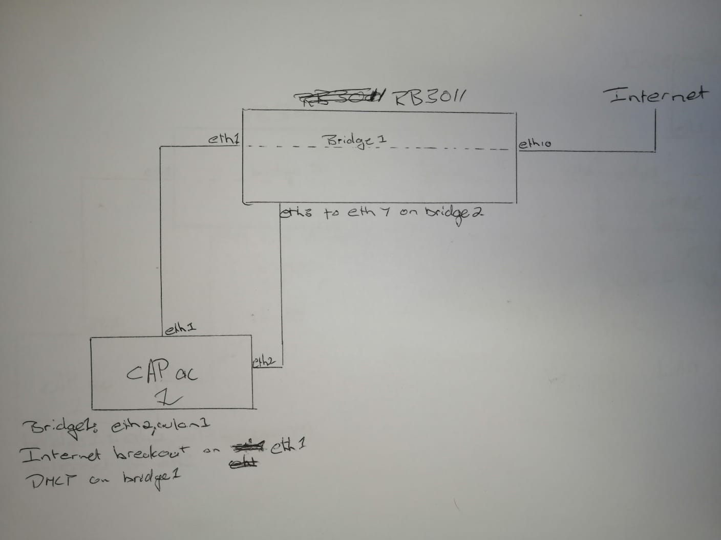
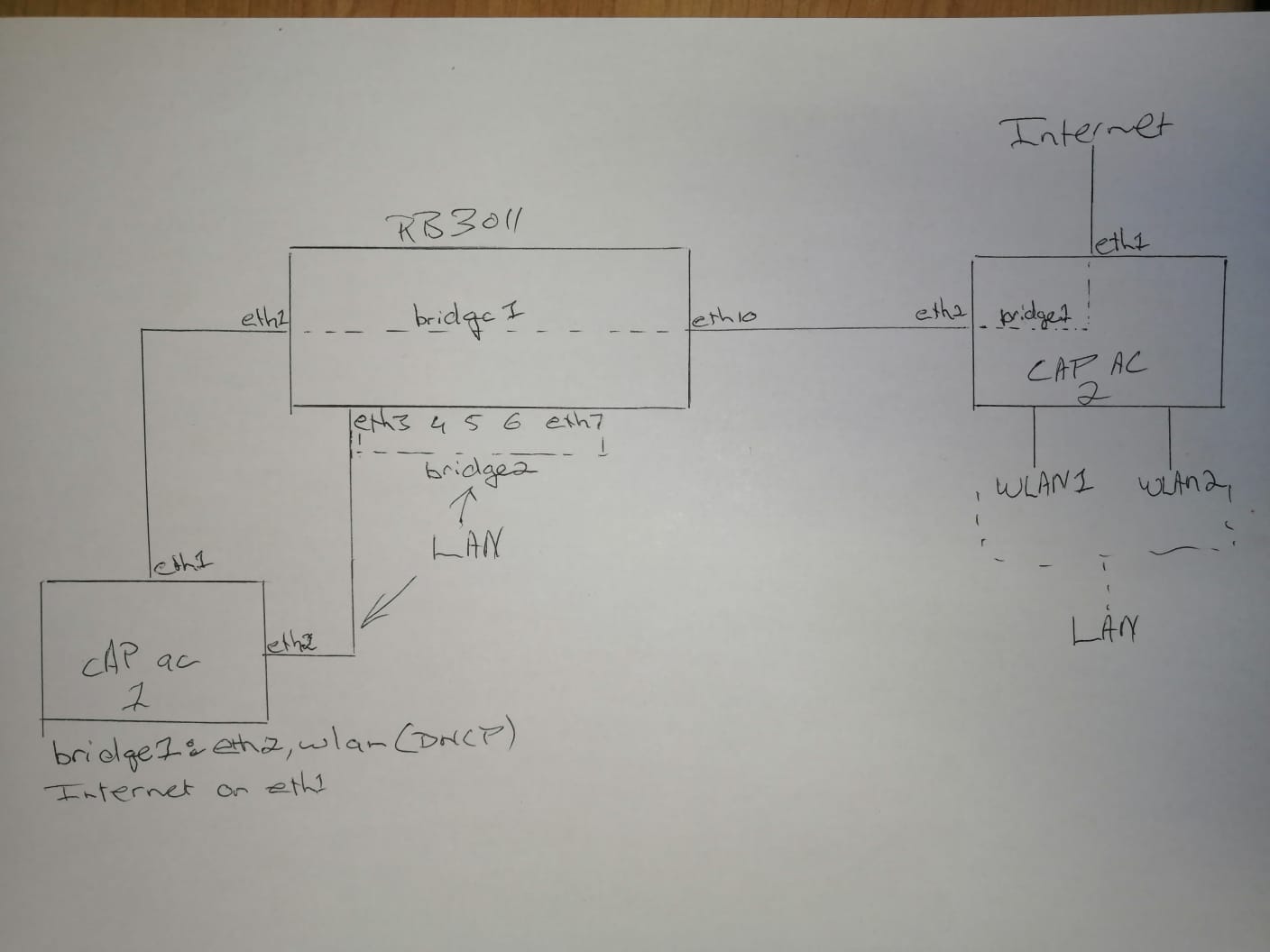
As per “current” attachment, this is my setup currently and its working. Wi-Fi on CAP1 and PCs on eth3 to 7(RB3011) all working fine with internet connection.
As per “future” attachment is what I want to implement with a VLAN, just not sure how to and would really appreciate any help.
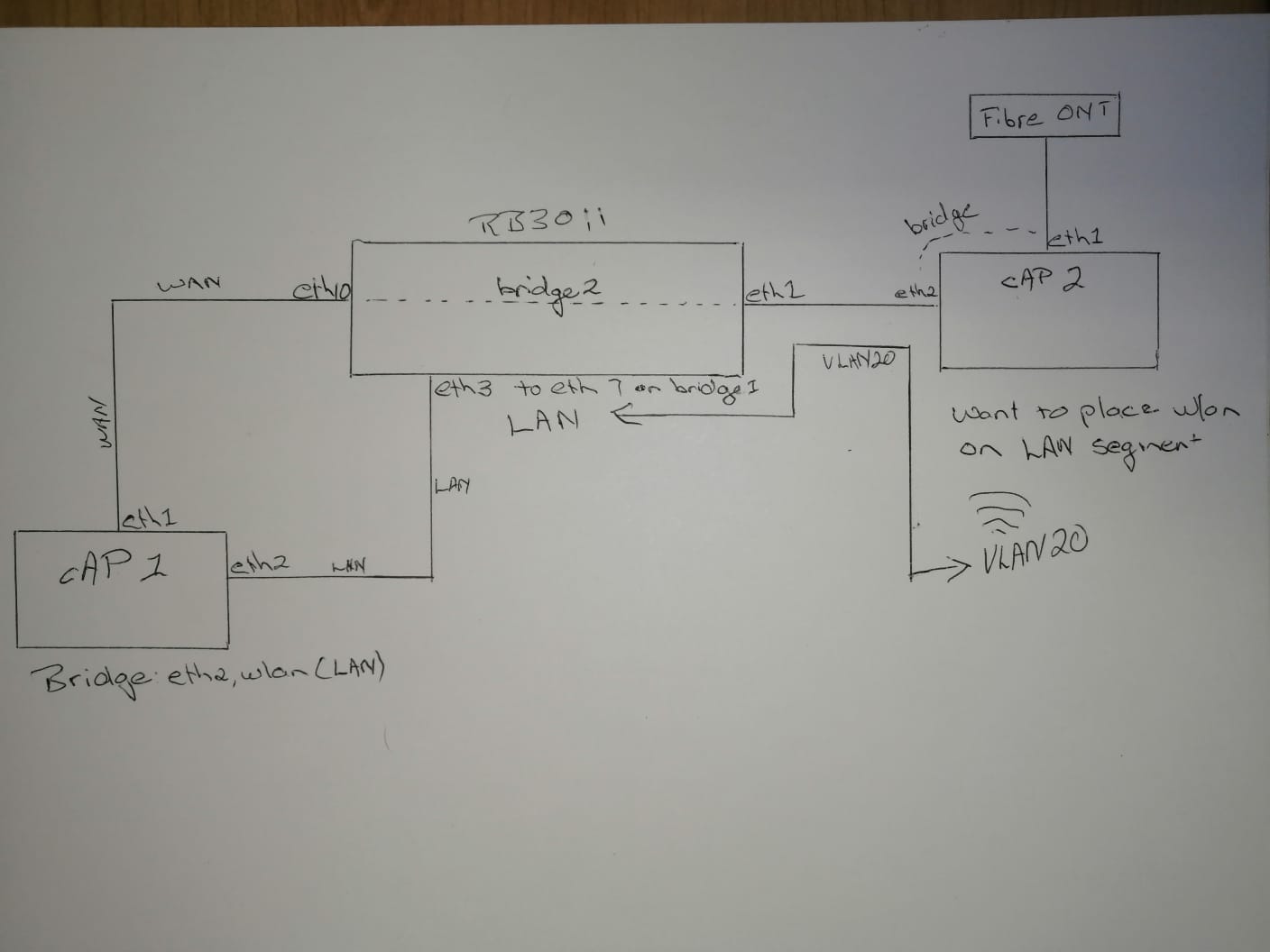
Basically I would like to add a cAP ac(cAP 2 on future) to serve Wi-Fi clients, but still be in the LAN segment i.e. get DHCP from CAP1(bridge1) and internet breakout on CAP1(eth1). Still using the same network cable from fibre box going to RGB3011 eth10.
Also you can export your existing configuration so we can see what we are working with.
I don’t understand why are you sending all traffic to CAP1 and then returning it to bridge2 ? One bridge is enough.
What you could do with CAP2 is to create VLAN on which you will send traffic to the router and another VLAN which will send traffic back to the CAP2, so basically you would use CAP2 as Switch/AP.
If I may, your current setup seems to me - let’s say - unconventional, and the intended one even more so, maybe there are reasons why you chose this topology (like some particular limitation with cables and placement of the devices), it would be useful if you could state these reasons, as there may be simpler topologies that would reflect as simpler configurations and easier maintenance.
A typical simpler scheme would be:
Internet
|
RB3011 ← Main router and dhcp server
|
Cap AC ← access point (bridge between cabled lan and wifi)
that could become either:
Internet
|
RB3011 as Main router and dhcp server
|
Cap AC as access point (bridge between cabled lan and wifi) ↔ 2nd Cap AC as access point (bridge between cabled lan and wifi)
or:
Internet
|
RB3011 as main router and dhcp server ↔ 2nd Cap AC as access point (bridge between cabled lan and wifi)
|
Cap AC as access point (bridge between cabled lan and wifi)
Thanks Jaclaz. Reason is limitation with cables and placement of devices. I only have one cable coming from RB3011(in roof) to the fibre ONT box, and I need to place a cAP close to the fibre ONT box, to serve internet to devices.
I have attaced a new diagram with few minor corrections.
So basically I think I only need to get a VLAN up and running from cAP2 to bridge1 on RB3011?
cAP2 has not been connected yet so attached are the configs for RB3011 and cAP1.
I know the easy way would be to swop cAP1 and cAP2 around and make then make everything behind cAP1 as LAN, but I want to learn how configure it in this more complex way via VLAN.
I still don’t understand.
The “natural” role of the RB3011 would normally be that of a router, but in your current scheme you are using it as a switch (with two bridges, one for LAN and one for WAN) and all the routing happens in your CAP1.
If the CAP1 is fast/good enough for your needs, then you can place it near the ONT ( between the ONT and the RB3011) and continue using it as a router.
I.e.
ONT
| WAN
CAP1 (as router and bridge between LAN and WLAN) → wireless AP1
|LAN
RB3011 (as switch, only one bridge needed)
|LAN
CAP2 (as bridge between LAN and WLAN)-> wireless AP2
The | in the above scheme are single cables and there is no need of VLANs, nor of two bridges on the RB3011.