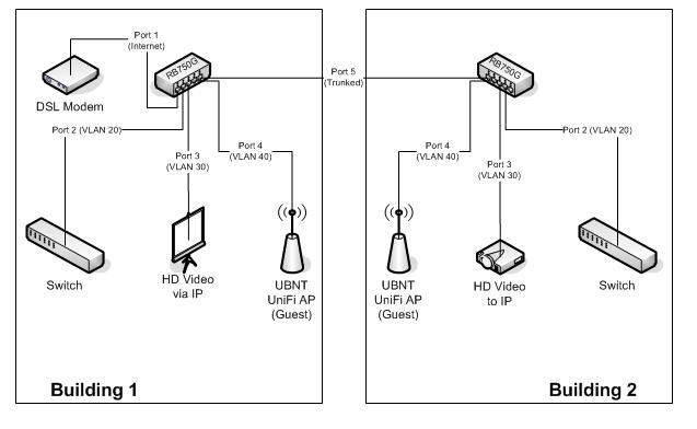
I’m having an issue getting two 750G’s to trunk between each other. Please see attached file.
I’m able to set up the VLANs on one side and get the ports to bridge to the respective VLANs but I’m having trouble getting the data across the trunk port on the other side. I also eventually want the AP to have both VLAN 20 and 30 so I can create separate SSIDs for employees and guests.
For the trunk port I just bridged all the vlans on port 5 in building #1 but I’m not sure what to do on the other side so I created all 3 VLANs again and bridged them on port 5 in building #2. All VLANs have DHCP hosted from building #1 so I tried to grab DHCP from any of the ports in building 1 with no success. I also tried to ping the other side with no success after I gave my computer a static IP.
You posted such a nice diagram I feel compelled to help!
It is unclear if the devices in ports 2-4 are vlan aware and what needs to talk to what.
Are the devices in 2-4 untagged and you simply want them to be tagged as vlan 20,30,40 when they cross the trunk?
Or ports 2-4 need vlans 20-40 and you then want them to trunk out 5?
Instead of the RB750G units, I would rather use VLAN aware switches, it’s much easier. I understand that you need one for your internet connection, and I have a feeling that your switches is not VLAN aware, that’s why you use a second RB750G.
I’m not quite sure, but I think you need to create a bridge, assign both the VLAN interface and the physical switch port to untag traffic. Maybe somoene with experience can tell us how that can be done.
I’m able to segment the traffic on each of the VLANs to a specific port on the SAME switch but I’m not able to see it on the RB750G in the opposite building. I’m pretty sure I’m just having issues with trunking between the two RB750Gs. The two switches that hang off the Mikrotik’s are flat access layer switches uses to attach the office computers and sound equipment computers. I’ve tried to bridge all the VLANs on port 5 but still nothing on the other end but still can’t see anything.
I’m usually a Cisco guy but this is for a Church with a detached office building and they can’t afford expensive Cisco products. I used MS Visio 2003 to do the drawings.
I purchased one RB750G unit today, let’s see what I can do with it. Port 1 are independent from the other ports. I think I need to separate the other ports from the switch group, to get different VLANs working. Otherwise, they will belong to the same default VLAN group.
I might just get a RB250G…but this has to work! I think I’ll still run into the issue of not being able to create a trunk port correctly.
Port 1 on the RB750G is independent only because it’s not a slave of another port. If you select “Remove Config” at the initial login (make sure you connect via mac address or you’ll get kicked out) then all the ports will be independent and you can start from scratch. The initial install template is for beginners wanting to set up a router for a home/office connection to the internet w/ port 1 as the internet gateway.
This does work, I have done this many times with ROS.
To start, you cannot put vlans on ports 2-4 and then bridge those vlans with port 5, expecting port 5 to be a trunk.
ROS is not a switch (although there is a switch chip it is outside of ROS), and vlan tags are removed on ingress.
If you want port 5 to be a trunk, then the vlans need to be on port 5.
IF Ports 2-4 do not have VLAN aware devices
If ports 2-4 do not have vlan aware devices, then do not put vlans on these ports.
Put vlans 20,30,40 on port 5 and bridge the ports with the vlans.
Port 2 bridged with vlan 20
Port 3 bridged with vlan 30
Port 4 bridged with vlan 40
3 separate bridges.
Then, in building 1, packets ingress port 2 untagged are bridged to vlan 20 on port 5, travel tagged across the trunk, ingress vlan 20 on port 5 in building 2 are bridged to port 2 and egress untagged.
If ports 2-4 have vlan aware devices then it is a little more complicated, but still doable in ROS.
Thanks reverged! That worked and the explanation made complete sense. I’m just use to Cisco where you just tell it that a certain port is a trunk port and define what vlans to send across the trunk.
So there’s a chance I’m going to need to replace the switch in building #1 with a VLAN aware switch and pass VLAN 20 and 30 across to it. Where would I do this?
I’m glad it worked out and thanks for the feedback.
Sometimes I answer posts here and never hear back. I wonder “did it work or go horribly wrong?”
If you replace the switch in building 1, then setup the trunk on the switch.
Any traffic that goes through the switch will do so at wire speed and reduce the load on the 750.
Setup 2 trunks on the switch, 1 goes to the 750 and 1 goes to bldg 2.
The 750 would have access to all the vlans that are on its trunk port (currently port 5) and config’d on the switch trunk port it is connected to.
Setup a management vlan so that from the bldg 1 750 you can manage the entire network.
This is all done and working now but I’m having some issues with CPU usage. Since everything is pretty much bridged, I’m starting to get high CPU whenever a video stream goes across from building 2 to building 1. I’m pushing about 3000pps and about 22Mb/s but my CPU goes up to 40% and my winbox session keeps disconnecting/freezing every 30sec to 1min. This happens on both v5.2 and 4.17 and only occurs when there’s a video stream going on. Otherwise everything works and is super stable.
The original Visio drawing shows two RB750’s but I’ve replaced the one in building 1 with a RB493AH because I needed more ports. My final setup ended up to be a EoIP tunnel between the two switches and and three vlans attached to the EoIP tunnel. All the ports are bridged out from the vlans. The reason I needed the EoIP tunnel is because the bridge between the buildings is a pair of UBNT NanoM5 about 50ft apart shooting across a parking lot. The NanoM5 isn’t the problem because I can do a MT bandwidth test at +75Mb/s from PC to PC with the MT’s inline at 5-7% CPU w/o having VLANs in place.
The mikrotik switches are great if you are doing vlans and trunking.
I only wish they had them with higher port density.
I have a network with a mix of SwOS and RouterOS and a main vlan switch (trunking etc etc…back to a firewall). There are some 750Gs on that network that are just running in a simple master/slave port setup right now (functioning as a switch)…a few unifi devices are going in and they need to be set up with vlan tagging and trunking back to the main switch…I’m tempted to just grab a few more 250Gs for them since it looks like it won’t be easy to get the 750Gs going with that config.