Thanks for link.
Good review of basics and it is very helpful where they post examples of configuration. Both sides of switch helps 
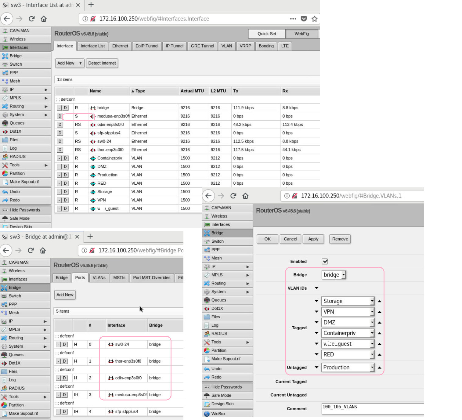
I believe for my example my environment is a bit of a mess now in that the managment VLAN 1
Question: Is there a command to enable or disable mangment access on a given interface. Ex: bind IP to VLAN (as router interface then) is that by default capable of response to mgmt traffic?
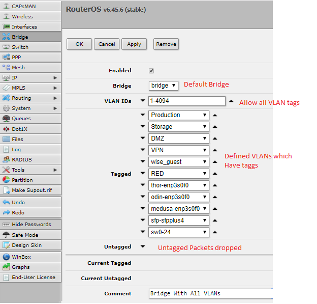
Second issue is that mgmt IP is today bound to my first 10Gb NIC port which is bound to bridge "bridge" and so that is how mangment is working. All physical ports on the same logical bridge called "Bridge" is how it is functioning, but I would prefer mgmt was bound to a VLAN and no matter which VLAN I am on, I can get to manage the switch. Move default VLAN to 100 and VLAN 1 would be the only "untagged" interface and go only on the 1Gb. Question this does bring up is do BDPUs for this switch still get pinned to VLAN 1 or are they per VLAN? This plays into OVS configuration with LLDP and virtual switches where I hope that I could later on do dynamic VLAN scripting via OVS.
Command for default Mgmt on VLAN 1 but I read bellow as also allowing mgmt on VLAN 100
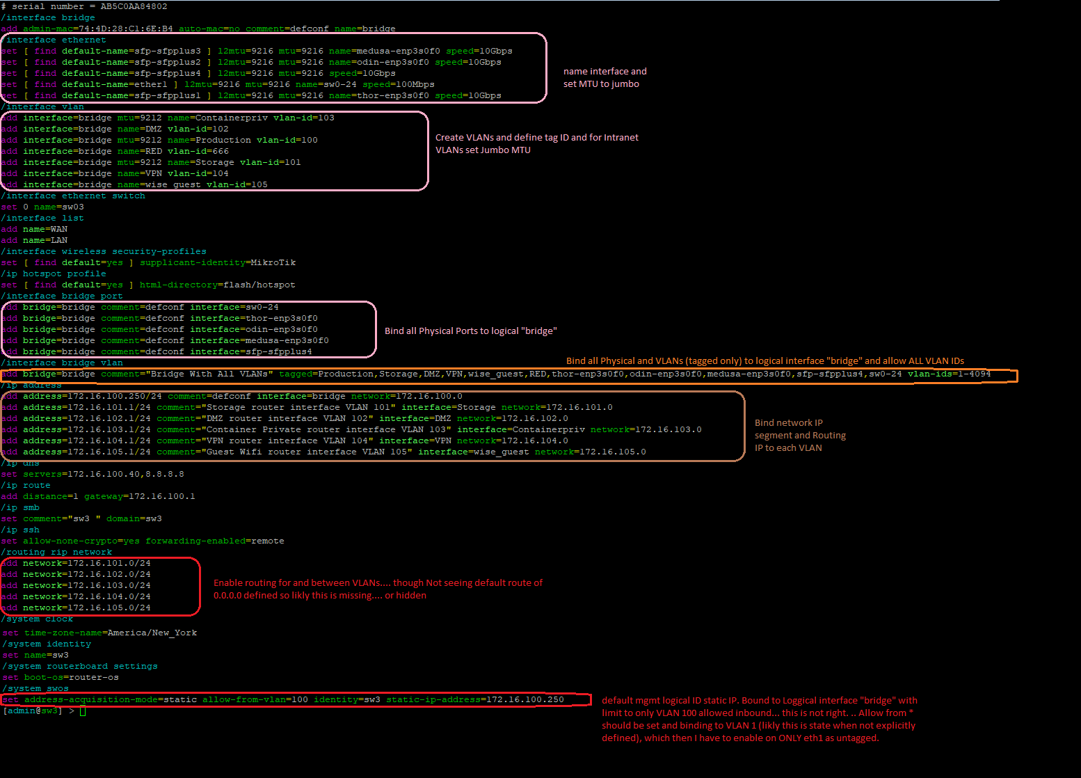
set address-acquisition-mode=static allow-from-vlan=100 identity=sw3
static-ip-address=172.16.100.250
\
Commands to fix "trunks" (assuming I get mgmt over all IPs validated to be ok)
Create a new logical bridge
/interface bridge port
add bridge=BR1 interface=sfp-sfpplus1
add bridge=BR1 interface=sfp-sfpplus2
add bridge=BR1 interface=sfp-sfpplus3
add bridge=BR1 interface=sfp-sfpplus4
add bridge=BR1 interface=ether1
Bind List of VLANs to the new BR1 logical bridge for each interface
add bridge=BR1 tagged=BR1,sfp-sfpplus1,sfp-sfpplus2,sfp-sfpplus3,sfp-sfpplus4,ether1 vlan-ids=100
add bridge=BR1 tagged=BR1,sfp-sfpplus1,sfp-sfpplus2,sfp-sfpplus3,sfp-sfpplus4,ether1 vlan-ids=101
add bridge=BR1 tagged=BR1,sfp-sfpplus1,sfp-sfpplus2,sfp-sfpplus3,sfp-sfpplus4,ether1 vlan-ids=102
add bridge=BR1 tagged=BR1,sfp-sfpplus1,sfp-sfpplus2,sfp-sfpplus3,sfp-sfpplus4,ether1 vlan-ids=103
add bridge=BR1 tagged=BR1,sfp-sfpplus1,sfp-sfpplus2,sfp-sfpplus3,sfp-sfpplus4,ether1 vlan-ids=104
add bridge=BR1 tagged=BR1,sfp-sfpplus1,sfp-sfpplus2,sfp-sfpplus3,sfp-sfpplus4,ether1 vlan-ids=105
Create VLANs with better layout to have DHCP pools as well as. Repeat below for each VLAN
/interface vlan add interface=BR1 name=Production vlan-id=100
/ip address add interface=Production address=172.16.100.1/24
/ip pool add name=Production ranges=172.16.100.50-172.16.100.200
/ip dhcp-server add address-pool=Production_Pool interface=Production name=Production_DHCP disabled=no
/ip dhcp-server network add address=172.16.100.0/24 dns-server=172.16.100.41 gateway=172.16.100.42
Questions:
- What will this do for VLANs I had already defined and have bound to bridge "bridge"?
- I am glad DHCP is a service offering on this switch, but is there a link to when I need to pass more advanced options such as bootp / NTP parameters? A link to example documentation is likly all I need.
- This switch does not seem to have a function of apply to running vs boot. AKA.. all commands are real time and if I scew it up I am finding a paper clip to do a hard reset (vs power cycle back to last saved configuration state.
- Also open to rec
I saw that there is a OVS of a virtual machine switch simulator. I assume that this would be a good place to run testing /simulations with but how close can I match hardware.. Is there a good site / documentation on how to set these up. I searched site / youtube about that and did not find much.