I have a RB751-2HnD that has a Atheros7240 switch chip.
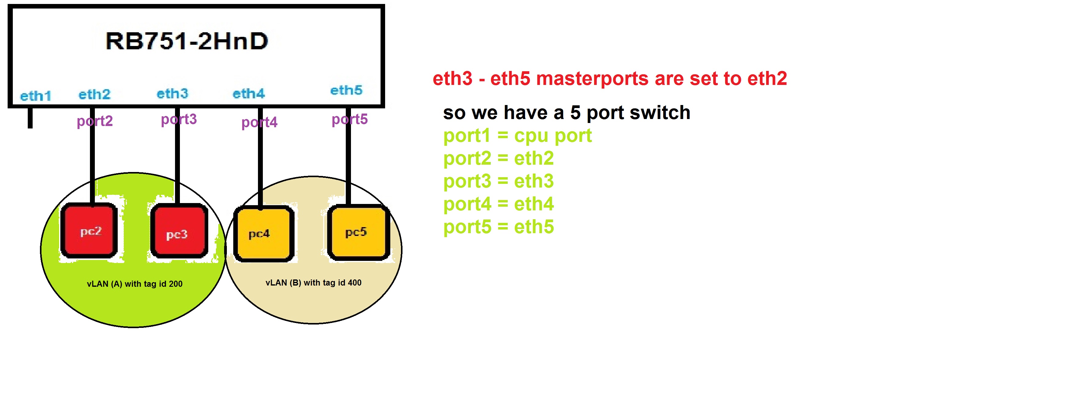
As you can see in the above picture I set master port for eth3-eth5 to eth2. so I have a 5 port switch with port:
1- port1 = cpu port
2- port2 = eth2
3- port3 = eth3
4- port4 = eth4
5- port5 = eth5
The simple scenario is:
All of my pcs have a IP address in range 192.168.1.x/24 so that in the normal situation they can communicate with each other. but
I want to have 2 vLANs, vLAN(A) and vLAN(B).
pc2 and pc3 are in vLAN(A) with vLAN tag id 200 and pc4 and pc5 are in vLAN(B) with vLAN tag id 400.
With this scenario I want to reach this goal:
The pc2 and pc3 can communicate with each other and pc4 and pc5 also too. and neither of pc2 or pc3 can not communicate with pc4 or pc5 and vise avers.
What do you mean by port1 = cpu port ??
If ether2 is the master port, then the cpu port of the switch chip is ether2 of router’s CPU. I think that you’re a bit confused with the terminology .
You can check my MUM presentation about the switch chip: http://mum.mikrotik.com/presentations/IT14/starnowski.pdf
But OK, let’s assume that ether3-ether5 have “master port” set to ether2. Then:
In the Switch menu, in tab called “VLAN”, create vlan 200 with ports ether2 and ether3, and vlan 400 with ports ether4 and ether5.
In the “port” tab you edit all 4 ports ether2-ether5, set VLAN Mode to “secure”, VLAN Header to “always strip”, and Default VLAN ID to 200 (ether2 and ether3) or 400 (ether4 and ether5).
That way pc2 and pc3 can see each other, pc4 and pc5 can see each other, but nothing more .
If you want the RouterBoard to be the gateway for the PCs, it’s a bit more complicated:
3. In the “VLAN” tab add “cpu” port to vlans 200 and 400
4. In the “port” tab edit the cpu port, set VLAN Mode to “secure” and “VLAN Header” to “leave-as-is”.
5. Create /interface vlan add name=vlan200 interface=ether2 tag=200 (and 400 the same way). You do it on ether2, as it’s the master port = the CPU’s port connected to the switch (see my presentation).
6. Create /interface bridge add name=bridge1
7. Add /interface bridge port add bridge=bridge1 interface=vlan200 horizon=1 (and vlan400 the same way). By setting the horizon to the same value - you make the 2 vlans separated from each other, but the MikroTik will have access to both.
8. You set the IP adress (ex. 192.168.1.1/24 - if it’s the gateway address - the address on your router) on the bridge1 interface.
What isn’t clear from the original post is whether the two VLANs need to communicate with the router or (say) an ISP on Ether 1 via NAT.
If they do:
Create VLAN interfaces for VLAN 200 & VLAN 400 on Ether 2
Under Switch, create VLAN 200 and add ports “switch 1 CPU”, Ether 2 & Ether 3 to it
Under Switch, create VLAN 400 and add ports “switch 1 CPU”, Ether 4 & Ether 5 to it
Under Switch set Ether 2, Ether 3, Ether 4 & Ether 5 to VLAN mode = Secure and VLAN Header “always strip”
Under Switch set “Switch 1 CPU” to VLAN mode = Secure and VLAN Header “leave as is”
Under Switch set Ether 2 & Ether 3 Default VLAN ID to 200
Under Switch set Ether 4 & Ether 5 Default VLAN ID to 400
You can now add IP addresses, DHCP servers etc. to the VLAN interfaces and control routing between them using filters in the forward chain.
That’s correct as long as you don’t want to have the routerboard see the traffic… When you use the switch chip VLAN interfaces serve generally to allow traffic from the routeros to the vlan.
Right. If you want tagged packets to travel from one port to another - you just use “/interface ethernet” to configure, which ports are controlled by switch, and then “/interface ethernet switch” to do the rest.
You use “/interface vlan” only if:
You want to add an IP address for the VLAN (for example - to route the traffic, to be able to ping hosts on the vlan from your MikroTik, etc.
If you want to bridge the vlan (the one on the switch) with other ports (wireless, tunnels, etc.)
If you want to sniff/torch something on the vlan (the switch should have then a mirroring or a rule with “copy to cpu”).
Good to know, that the presentation actually helped someone. Thanks
I have been searching for an explanation for so long and couldn’t understand how it all works.
So definitely your presentation is the best thing I’ve seen so far - Mikrotik’s team should put it somewhere on the WiKi.
I even assume that some people think they are getting the best out of their router but they don’t clearly know how to use switch chip for VLANs.
Dasiu, now between “I understood” and “I’m able to apply it”, there’s a world
In your presentation you mention only one master port for a chip. How if I want to have two but only one with switch chip used for vlans?
I currently have a RB450G (planning to switch for a 2011UiAS), can you tell me if my config looks correct ?
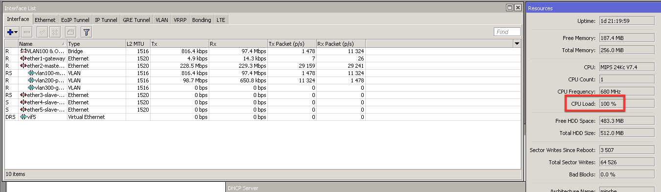
I am using ether1 for WAN, ether2 and ether3 to trunk VLAN, ether4 and ether5 with “non-vlan” ports for the moment:
/interface ethernet
set [ find default-name=ether1 ] mac-address=00:0C:42:BD:D3:F7 name=ether1-gateway
set [ find default-name=ether2 ] mac-address=00:0C:42:BD:D3:F8 name=ether2-master-trunk
set [ find default-name=ether3 ] mac-address=00:0C:42:BD:D3:F9 master-port=ether2-master-trunk name=ether3-slave-trunk
set [ find default-name=ether4 ] mac-address=00:0C:42:BD:D3:FA name=ether4-master-local
set [ find default-name=ether5 ] mac-address=00:0C:42:BD:D3:FB name=ether5-slave-local
/interface vlan
add interface=ether2-master-trunk l2mtu=1516 name=vlan100-management vlan-id=100
add interface=ether2-master-trunk l2mtu=1516 name=vlan200-private vlan-id=200
add interface=ether2-master-trunk l2mtu=1516 name=vlan300-guest vlan-id=300
/interface ethernet switch port
set 1 vlan-mode=secure
set 2 vlan-mode=secure
/interface ethernet switch vlan
add ports=switch1-cpu,ether2-master-trunk,ether3-slave-trunk switch=switch1 vlan-id=100
add ports=switch1-cpu,ether2-master-trunk,ether3-slave-trunk switch=switch1 vlan-id=200
add ports=switch1-cpu,ether2-master-trunk,ether3-slave-trunk switch=switch1 vlan-id=300Thanks!
Unfortunately you can only have a single master port per switch chip. If you need to logically separate the ports you’ll need to go with vlans. Of course, on an RB2011 there are two switch chips so you could wait for that.
As I said there - there can be only 1 master port in 1 switch chip… BUT, there is a trick . If I understand it right, you need to switch ports ether4 and ether5 with no vlan tags, and they will be separated from the ether1-ether3 traffic? If it is so - then you can set ports ether4 and ether5 to have master ether2 (yes!), and be access ports in vlan 999 - let’s say . As only the 2 ports have vlan999, and they don’t have any other vlan (no 100, 200, 300) and vlan mode is secure for all ports => ether1-ether3 trunk will be separated from ether4-ether5 switch. And vlan999 is not relevant, as they are both access - from the outside noone will see the tag, it’s only internal.
Still I am able to have two master ports in the configuration. Now, does it mean that if I do so I am not making use of switch chip to manage vlan traffic ?
The 2011 series has one switch chip for the GigE ports and one for the FastE ports. Any traffic that crosses between those two switch chips needs to go through the main processor. On the 2011 series switch chips the chip is capable of having only one master port per switch chip. If you try to configure more than one it will complain.
On the CRS you can have more than one… effectively what it does is that traffic between any slave port and a given master port is handled in the switch chip. Any traffic between master port groups would go through the main processor.
Don’t have a 450G so I don’t really know. Can’t find the block diagram online. My assumption would be that if it lets you declare it then it should be able to handle it. You can email support just to verify.
However when Computer sends data to NAS, in current case I was synchronizing a 6Gb mailbox and then TimeMachine backup, CPU load of Mikrotik goes crazy, see attached file… I didn’t expect this.