What you are describing is not vlans; it is port isolation.
When to use vlans: (separate virtual broadcast domains)
- You want to share physical hardware (switches, ports, links) with multiple logically separate LANs.
- A device that has direct access to more than one LAN will need a layer 3 interface with an ip address in each vlan it is directly connected to.
- Devices in one vlan can only communicate with another subnet (usually in a separate LAN whether vlan or dedicated LAN) with the assistance of a router and a route (usually will be default route).
When to use port isolation: (port filtered forwarding - possibly asymmetric)
- All ports (and devices) are in the same subnet.
- You want to limit what other ports some of the ports in the subnet are allowed to send data to.
- All ports you want to limit are on the same switch.
Again, what I am posting below is not vlans, but it is the answer to the specific question you pose.
First read port isolation
Then make a backup of your switch config, because you will probably want to restore to the previous state after the experiment. If you don’t know how, see this.
Disconnect all wires from the switch except for power and the console port or the port you are configuring the switch from. Reset to factory config so we know what the config is.
Connect the PCs to the first 4 ports.
In this state, all ports should be in a single broadcast domain. You will need to manually configure your PCs with static addresses, because they won’t have a dhcp server to give them any address.
Verify that you have communications between all four devices. From each PC ping the others, all this should work. If it does not, you have a firewall on the PCs.
Then open the Port Isolation tab. Take screen shot and save for your reference. Clean all check boxes (see note in documenation: “It is possible to check/uncheck multiple checkboxes by checking one of them and then dragging horizontally (Click & Drag).” For this experiment, clearing only the top 4 rows should be sufficient.
Make the check boxes look like the following:
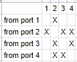
Then port 2 is the only port that can send and receive from the other 3 ports.
Port 1 can only send and recieve from port 2.
Ports 3 & 4 can only communicate to each other and port 2
Test and verify. The only pings that should work: PC on port 2 should be able to ping the other 3. PC on port1 should only be able to ping PC on port2. PCs on ports 2 and 3 should be able to ping each other and port2 PC but not port1 PC.
After you are satisfied that this “works”, you can restore your config.
Using vlans is probably what you really want to do, especially since you also have another vlan capable switch (the TP-Link SG108E), although is is possible to use a combination of port isolation and vlans. If your G3100 is on the same subnet as your hEX LAN, port isolation is the only way I am aware of to limit what the G3100 would be able to communicate with on the subnet. Vlans allow you to have multiple LANs (each with its own ip subnet) sharing the same switch and wires, but traffic between the vlans will need to be routed by the hEX. You can then use the firewall on the hEX to limit what traffic goes between the distinct subnets.
Have you looked at any of Ed Harmoush’s material?
I realize that this is just a thought experiment, but I don’t know how it is possible to configure more than a single “default VID” on a port.
In SwOS the Default VLAN ID is what most vendors call the pvid, and it is the single vlan that the port will classify/assign to an untagged frame the switch receives on the port. The pvid will also make the switch remove the tag when sending a frame for that vlan as well. SwOS has the ability to strip tags regardless of VID, using the “best avoided” feature in the VLAN tab with the column “Force VLAN ID”, which essentially tells the switch to strip any tag and to classify the frame into the Default VLAN, something that I can think of no good use for.
Thank you all again so much for your generous help.
This is a lot to take in. I clearly did not (possibly still don’t) have a correct understand of VLANS.
I understand VLANs segment (or create) networks on layer 2 (Data Link), thereby making each VLAN function as if it were a different physical LAN (whereby a router would be needed to pass traffic between the VLANs).
VLANs use tags (bits added to an ethernet frame (or packet)) that specify the VLAN ID (e.g., 0, 10, 20, 100, etc.) of the frame.
When a device such as a PC sends out a frame that does not have a VLAN tag the frame is an UNTAGGED frames.
When a device such as a switch or router (or other VLAN-aware devices) sends out a frame with a VLAN tag the frame is a TAGGED frame.
All frames with the same ID comprise a single VLAN.
An ACCESS port is used for devices that send and receive UNTAGGED frames. That same port will have a default ID – that is, that port will have a single VLAN ID.
Trunk ports have multiple IDs assigned to them. One ID is the NATIVE VLAN which passes traffic of frames that do not have a tag (and therefore do not have an ID). Frames with IDs matching the other IDs assigned to the trunk port are passed.
Different IP subnets (layer 3 --Network) are commonly used to facilitate routing between VLANs.
Therefore, when configuring VLANs on a switch, we set the following for each port:
VLAN MODE [Optional, Enabled, Disabled, Strict]:
RX VLAN MODE [Any, Only Untagged, Only Tagged]: This determines whether the switch will accept (allow in) frames that either have and/or don’t have VLAN tags.
DEFAULT VLAN ID [VLAN number]: Assigns ID to any untagged frames that arrive at the switch.
Therefore, any VLAN-UNAWARE devices (devices that do not attach or recognize VLAN tags) must be connected to ACCESS ports, and frames arriving at and sent from these switch ports will effectively be assigned the DEFAULT VLAN ID. That means that if port 1 is an access port with a DEFAULT VLAN ID of 10, and port 2 has a DEFAULT VLAN of 20, the VLAN-UNAWARE devices each plugged into ports 1 and 2 will not be able to communicate.
I am still confused about how VLAN membership comes into play.
Probably you can’t set multiple PVIDs exactly for the absurd example I was explaining. Not sure about SwOS, but in ROS it is possible to add a port as untagged member of multiple VLANs (that’s only egress behaviour though).
Don’t feel bad, without setting up a lab and capturing packets generated with scapy with wireshark, some of the terse descriptions just make me have more questions. For example, I think is is possible to have the CSS106 be “vlan transparent”, i.e. just pass the ethernet frames as is without regard to what is in the ethertype field, and base its forwarding decisions only on destination mac address, but I don’t see any option that would allow that. It would not surprise me if the descriptions in the manual are not 100% correct, especially in edge cases. But it probably is not possible to describe it accurately in the space they have used.
For the common cases you are likely to encounter (access port, fully tagged trunk port, Hybrid (trunk port with active native vlan), just mimic the settings in the examples and it will work.
Once a frame has been received, accepted and classified into a single vlan, then the frame can only be forwarded to other ports that are members of that vlan. By member, I mean what is displayed in the right hand part of the VLANS tab display (which essentially is telling the switch what ports a frame belonging to a specific vlan are allowed to be sent to). The VLAN tab is primarily telling the switch what to do with received frames, and whether the frame is tagged or not when it is received on the port). When sending a frame out of a port, the switch uses the following simple rule to decide whether it should put a tag on the frame or not. If the vlan being sent from on the switch matches the pvid on the port (port vlan id or in SwOS terminonlogy the Default VLAN), then the frame will be sent without a tag. Otherwise it will be sent with a tag for the vlan it was a member of while in the switch.
When using vlans, every host device that is connected to link with more than one vlan (a trunk link) will need to have an interface for every vlan it needs to communicate with. You can’t have one logical interface receive and send on two different vlans. (At least that is the case under normal circumstances that you are likely to encounter, there are things like asymmetric vlans where that isn’t true, but going into that at this stage won’t help your understanding at this point, just like talking about matrix multiplication when you are just learning your times tables would not be helpful).
Here’s a more concrete example. You have a Raspberry Pi with a single wired interface, and you also have an SG108E vlan aware switch. You want to create a router, but the Raspberry Pi has only a single physical interface. Here’s one thing that can be done without any additional hardware.
On the Raspberry Pi load the vlan package. This will allow you to create vlan subinterfaces like eth0.20 which will be the interface for vlan 20 and all packet sent from eth0.20 will leave through the eth0 physical interface, but will be tagged with vlan 20. To the rest of linux on the Raspberry Pi, the eth0.20 interface behaves like a standard ethernet connection. You assign an ip address to eth0.20 that is in a different subnet than eth0. For this example, let eth0 use 192.168.1.1/24 and eth0.20 use 192.168.20.1/24. Note that traffic from the eth0 interface will be untagged, while the traffic from eth0.20 will be tagged.
Then you can create a trunk port on the SG108E with PVID 1 and tagged 20. Then create two access ports on the SG108E, one in vlan 1 with PVID 1, and one in VLAN 20 with PVID 20.
At this point, you now have a Raspberry Pi with two ethernet ports (though the SG108E) and you could add more, since the SG108E has 8 ports, and 5 would still be free.
The hEX operates very much in the same way as the Raspberry Pi with the external switch. But on the hEX you create the vlan subinterface with the /interface vlan command, and the “switch” is the bridge device.