Wireguard Triangle

Have in production a VPN ipsec/ike2 triangle of 3 office sites all with fixed IPs and MT Routers ROS 7.3. (without VPN road warrior access)
I wish to convert to a “Wireguard Triangle” and add road warrior access to each site with my Android or Windows laptop for the purpose of admin to computers via a local node, but never more than one RW at a time on the whole triangle at a time. LAN subnets of each node would need to be accessible both to the immediate RW (if connected) and to the adjacent Mikrotik nodes. I dont believe I will need any relay function of any Mikrotik nodes in this setup. I would have three wireguard configurations on the Android and three on the laptop so as to gain RW access to each of the 3 nodes.
RW-A= road warrior android RW-W= road warrior windows

A diagram may give a better understanding of my requirements.
Wireguard Triangle 3.jpg
I have looked through the many reference articles around here on the forum
and think I can manage part of the setup being the red arrow setup with the road warriors hanging off each node.
ie
172.16.10.1 (the Wireguard server router itself Site-A) <-----------> Wireguard client on 172.16.10.2 Site-B
172.16.10.1 (the Wireguard server router itself Site A) <-----------> Wireguard client on 172.16.10.3 Site-C

The question is do I have to have a different wireguard subnet with extra wireguard interfaces on Site-B and Site-C or do I just configure Site B to Site C as “servers” talking to each other on the 172.16.10.0/24 subnet? ie how do I connect using wireguard where the green arrows are?
All routers have their default ROS configuration in place and I wish to use IPs for the WG network/s on all 3 MT Routers.

You started out clearly and then got messy.

Lets ensure the requirements are clear.

  1. Admin needs access to all routers for config purposes remotely
  2. Admin needs access to all subnets remotely
  3. Admin has one android phone and one laptop as the RWs

Need to establish
Which Router is desired as the SERVER for initial handshake so that the other two routers are connected full time.
Best choice is a static public IP with highest bandwidth on the WAN and best CPU. The trifecta :slight_smile:

One wireguard network is required.
R1 ( primary- server at handshake ) 10.20.30.1/24
R2 ( secondary) 10.120.30.2/24
R3 ( secondary) 10.20.30.3/24
C1 (RW-android) 10.20.30.4/32
C2 (RW-laptop) 10.20.30.5/32

Client settings R1
(R2) 10.20.30.2/32,localsubnetC,localsubnetD
(R3) 10.20.30.3/32,localsubnetE,localsubnetF
(C1) 10.20.30.4/32
(C2) 10.20.30.5/32

Routes R1
localsubnetC WG_R1 MAIN
localsubnetD WG_R1 MAIN
localsubnetE WG-R1 MAIN
localsubnetF WG-R1 MAIN

*FWRULES R1*
input Allow interface WG-R1
forward allow in-interface WG-R1 out-interface-list LAN ( assumes R1 has local subnets A,B )
forward allow in-interface WG-R1 out-interface WG-R1 ( allows admin to reach R1 and then re-enter tunnel to R2,R3 )
++++++++++++++++++++++++++++++++++++++++++++++

Client Settings R2, R3,C1,C2
(R1) 10.20.30.0/24 persistent keep alive=35sec

FWRULES R2
input allow interface WG-R2
forward allow in-interface WG-R2 out-interface-list LAN

FWRULES R3
input allow interface WG-R3
forward allow in-interface WG-R3 out-interface-list LAN

+++++++++++++++++++++++++++++++++++++++++++++++++++++++++

Thank you for your detailed response.
I apologise for not clearly outlining my requirements.

From what I can gather you have proposed a hub (Server- Site A) and spoke topology (Clients - Site B, Site C, RWx2) where the spokes/clients all hang off the hub with Site A acting as a relay server if Site B( or it’s local subnet) wants to talk to Site C (or it’s local subnet). I would prefer a direct tunnel between Site B and Site C like I had for Ipsec/Ike2 setup. I dont see requiring separate RW access at each node a disadvantage for administration.

I was really after a “triangle” topology where Site B has a direct tunnel with Site C as would suite my needs better to improve performance when a Site B workstation program needs to access database backend at a Site C workstation or with a file transfer. I assume it would be possible if I follow the rules like having listening ports and seeking the correct endpoints with keep alive to establish and maintain tunnels and creating routes to local subnets and no overlapping allowed IPs per node WG interface and associating WG Lan with Wan in the interface list for ROS. Thus the 3 nodes would have a mixture of server/client functions.

Can anyone please confirm that wireguard might work with “triangle” topology. Thank you

R1 has direct access to R2 and R3 and vice versa.
I dont see the point of creating another wireguard interface just so R2 and R2 can converse directly but so be it

If you do then it will look differently.


TWO wireguard networks are required ( at least on routers 2 and 3 )
Network1
R1 ( primary- server at handshake ) 10.20.30.1/24 WG-R1
R2 ( secondary) 10.120.30.2/24 WG-R2
R3 ( secondary) 10.20.30.3/24 WG-R3
C1 (RW-R-android) 10.20.30.4/32
C2 (RW-R-laptop) 10.20.30.5/32

Network2
R2 ( primary - server at handshake) 10.50.50.1/24 WG-D2
R3 ( secondary - client at handshake) 10.50.50.2/24 WG-D3
D1 (RW-D-android) 10.50.50.3/32
D2 (RW-D-laptop) 10.50.50.4/32

Client settings on Server R1 ( WG-R network )

(R2) 10.20.30.2/32,localsubnetC,localsubnetD
(R3) 10.20.30.3/32,localsubnetE,localsubnetF
(C1) 10.20.30.4/32
(C2) 10.20.30.5/32

Routes R1
localsubnetC WG-R1 MAIN
localsubnetD WG-R1 MAIN
localsubnetE WG-R1 MAIN
localsubnetF WG-R1 MAIN

FWRULES R1
input Allow dst-port=wireguard-listening-port (WG-R) protocol=udp
input Allow interface WG-R1 src-address-list=Authorized { allow RW-A to access R1 for config }
forward allow in-interface WG-R1 out-interface-list LAN ( allows remote subnets of R2,R3 to reach local LAN at R1 }
forward allow in-interface-list=LAN out-interface=WG-R1 ( allow local lan subnets to go out wireguard )
++++++++++++++++++++++++++++++++++++++++++++++

Client Settings R2, R3,C1,C2 ( WG-R Network )
R2 - 10.20.30.1/32,localsubnetA,localsubnetB persistent keep alive=35sec
R3 - 10.20.30.1/32,localsubnetA,localsubnetB persistent keep alive=35sec
C1 - 0.0.0.0/0 persistent keep alive=35sec
C2 - 0.0.0.0/0 persistent keep alive=35sec

Client settings on Server R2 ( WG - D Network )
(R3) 10.50.50.2/32,localsubnetE,localsubnetF
(D1) 10.50.50.3/32
(D2) 10.50.50.4/32

Client settings R3,D1,D2 (WG - D Network )
R3 - 10.50.50.1/32,localsubnetC,localsubnetD persistent keep alive=30sec
D1 - 0.0.0.0/0 persistent keep alive=30sec
D2 - 0.0.0.0/0 persistent keep alive=30sec

FWRULES R2
input Allow dst-port=wireguard-listenting-port(WG-D) protocol=udp
input allow interface WG-R2 source-address-list=Authorized { if you wish RW-R to access config of R2 }
input allow interface WG-D2 source-address-list=Authorized { if you wish RW-D to access config of R2 }
forward allow in-interface WG-R2 out-interface-list LAN { allow R1 subnets to reach R2 subnets }
forward allow in-interface WG-D2 out-interface-list=LAN {allow R3 subnets to reach R2 subnets }
forward allow out-interface WG-R2 in-interface-list LAN { allow R2 subnets to access R1 LAN }
forward allow out-interface WG-D2 in-interface-list=LAN {allow R2 subnets to access R3 LAN }

FWRULES R3
input allow interface WG-R3 source-address-list=Authorized { if you wish RW-A to access config of R3 }
input allow interface WG-D3 source-address-list=Authorized { if you wish RW-B to access config of R3 }
forward allow in-interface WG-R3 out-interface-list LAN { allow R1 subnets to reach R3 subnets }
forward allow in-interface WG-D3 out-interface-list=LAN {allow R2 subnets to reach R3 subnets }
forward allow out-interface WG-R3 in-interface-list LAN { allow R3 subnets to reach R1 subnets }
forward allow out-interface WG-D3 in-interface-list=LAN {allow R3 subnets to reach R2 subnets }

ROUTES R2
localsubnetA WG-R2 MAIN
localsubnetB WG-R2 MAIN
localsubnetE WG-D2 MAIN
localsubnetF WG-D2 MAIN

ROUTES R3
localsubnetA WG-R3 MAIN
localsubnetB WG-R3 MAIN
localsubnetC WG-D3 MAIN
localsubnetD WG-D3 MAIN
+++++++++++++++++++++++++++++++++++++++++++++++++++++++++

To get my head around this I need to go back a step:
I have 3 sites all with static public IPs. I wish to establish a mesh like triangle with three nodes, so each node is in direct contact with the other 2 nodes.
A lot of the examples of wireguard networks are limited to direct site to site or site to or multisite with relay connections and nodes without static public IPs.

Using the diagram above and the displayed network addresses I have outlined the details that I think might work to connect the 3 nodes in this mesh network. I have tried to keep this is simple as possible by using the same wireguard subnet and leaving out the road warrior requirements at this stage. I can’t find details of a similar example. I have arranged the initiation and maintenance of the tunnels in a one way clockwise fashion and all the 3 node listening on 13231 for UDP traffic. For those with real world experience and more knowledge I would be grateful for feedback. Will this work? Have I transgressed from the wireguard rule book?

Router-A (Site-A)
WG interface 172.16.10.1/24
Peers x2
Allowed IP
172.16.10.3/32, 192.168.2.0/24
172.16.10.2/32, 192.168.1.0/24 endpoint Site-B public IP:13231 keep alive 20
Routes (to lans on adjacent nodes)
Dst 192.168.1.0/24 Gateway 172.16.10.2
Dst 192.168.2.0/24 Gateway 172.16.10.3


Router-B (Site-B)
WG interface 172.16.10.2/24
Peers x2
Allowed IP
172.16.10.1/32, 192.168.0.0/24
172.16.10.3/32 192.168.2.0/24 endpoint Site-C public IP:13231 keep alive 20
Routes ( to lans on adjacent nodes)
Dst 192.168.0.0/24 Gateway 172.16.10.1
Dst 192.168.2.0/24 Gateway 172.16.10.3

Router-C (Site-C)
WG interface 172.16.10.3/24
Peers x2
Allowed IP
172.16.10.2/32, 192.168.1.0/24
172.16.10.1/32, 192.168.0.0/24 endpoint Site-A public IP:13231 keep alive 20
Routes
Dst 192.168.0.0/24 Gateway 172.16.10.1
Dst 192.168.1.0/24 Gateway 172.16.10.2

add the wireguard interface itself to LAN interface list on each node - Mikrotik Routers ROS 7.3 with default configuration.
Thanks for help

YOur approach is wrong and it starts with false requirements.
You are saying you need 3 sites in a mesh node type of configuration.

That is your mistake, that is not a requirement it is solution speak. YOu are already predetermining what you need for the config.
Instead of stating what are the actual traffic flow requirements. This often leads to attempting to put round pegs into square holes and in this case wireguard seems to be your solution of choice and yet it is not a node mesh protocol, its peer to peer!


So lets go back to basics and understand the actual requirements for traffic
From that an ideal config can be designed.

  1. Identify all the users/devices, groups of users/groups of devices (including the admin) that require traffic flow.
  2. Identify what traffic flows are permitted desired between the users and devices in step 1.

Then we will see if there is sufficient information to formulate a plan.

Hello,
I have similar configuration.
A triangle of 3 equal routers with public IPs. They have private LANs behind with addressing that is planned ahead and does not overlap. These LANs go to the internet using via NAT of their respective routers, no special need here. The goal is to have full connectivity between all these private LANs, internet access from LANs and road-warriors are out of scope, no dial-up clients. Only 3 LANs.
Statically it is relatively easy to build very basic setup: each router has 2 wireguard tunnels to its peers, so 2 wireguard interfaces with different ports. I use the same wireguard network for all wireguard interfaces. I now have full connectivity, but no fail-over (redundancy).

The question is the redundancy by mesh in case when 1 of the tunnels is blocked/down, so that the full connectivity is maintained using 2 other working tunnels. Additional requirement is that this redundancy be automatic, so when one of the wireguard tunnels fails, the traffic gets rerouted automatically using other tunnels, and gets back to normal when broken tunnel is restored. I have tried to add secondary routes with different distance, but they never get activated when the connection is blocked/down because the wireguard interfaces stay up.
As i understand, in a triangle configuration mesh=peer to peer, for the whole mesh we only need 3 P2P tunnels.
How to obtain the desired connectivity redundancy? Do i need 3 separate wireguard networks for this? How do i use static routing to achieve my goal? Or you would suggest dynamic routing?
Thanks for suggestions.

Okay so your concern is what if the server Router is removed from the picture.
The main reason why a tunnel would fail is if WAN connection was stopped or the router broke.

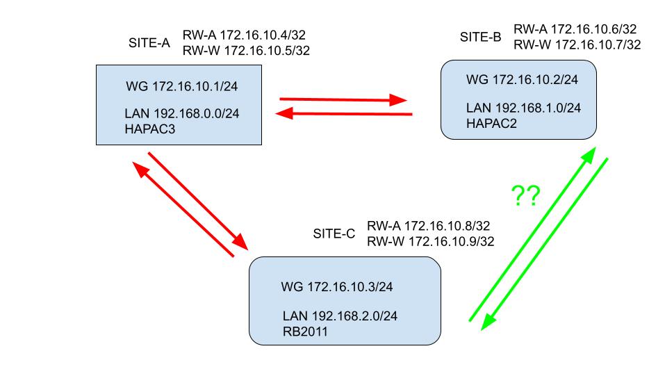
a. If the traffic failed on Server Router1 for handshake (either router1 failure or internet failure at R1) routers 2,3 would not be connected
b. If the traffic failed on a Client router 2 for handshake (either router2 failure or internet failure at R2 ) routers 1,3 would still be connected.
c. If the traffic failed on a Client router 3 for handshake (either router3 failure or internet failure at R3 ) routers 1,2 would still be connected.

Therefore the only possible redundant solution is another wireguard circuit between 2 and 3.
In the above scenario, lets play it out
a. Router1 is out of the picture, Router 3 connects to Router2 on secondary wireguard interface.
b. no effect 1 & 3 still talking
c. no effect 1 & 2 still talking

Therefore logically speaking we need one other wireguard interface/network and it can be up all the time ready to pitch in.

If you are willing to rely on a third party, you can run Zerotier network joining all three LANS such that they are on the same L2 subnet, whereas Wireguard connects them at L3.
The connection is from each router to Zerotier and thus any router failing has no effect on the other two connecting.

+++++++++++++++++++++++++++++++++++++++++++++++++++++++++++++++++++++++++++++++++++++++++++++++++++

R1
Wireguard Interface=WG-MAIN1 listening port= 14555 comment=server on wireguard main.

allowed IPs=r2-wg-main2-IP/32,r2subnet comment=“client peer router2”
allowed IPs=r3-wg-main3-IP/32,r3subnet comment=“client peer router3”

/ip address
add address=10.10.10.1/24 interface=WG-MAIN1 network 10.10.10.0

/ip firewall
add action=accept chain=input dst-port=14555 protocol=udp comment='wireguard MAIN handshake"
add action=accept chain=forward src-address=localsubnet out-interface=WG-MAIN1 comment=“allow local subnet traffic to enter tunnel”
add action=accept chain=forward dst-address=localsubnet in-interface=WG-MAIN1 comment=“allow R2 and R3 subnet incoming traffic”
add action=accept chain=forward in-interface=WG-MAIN1 out-interface=WG-MAIN1 comment=“allow R2 to reach R3 and R3 to reach R2”

/ip route
add dst-address=r2subnet/24 gateway=WG-MAIN1 routing-table=main

R2
Wireguard Interface=WG-MAIN2 listing port=1455
Wireguard Interface=WG-ALT2 listening port=12555 Comment=server on wireguard alternate.

allowed IPs=wg-main1-subnet/24,r1subnet,r3subnet endpoint=publicIP-R1 endpointport=14555 persistent-keep-alive=35 comment=“server peer router1”
allowed IPs=wg-alt3-ip/32,r3subnet comment=“client peer router3”

/ip address
add address=10.10.10.2/24 interface=WG-MAIN2 network=10.10.10.0
add address=10.20.10.1/24 interface=WG-ALT2 network=10.20.10.0

/ip firewall
add action=accept chain=input dst-port=12555 protocol=udp comment='wireguard ALT handshake"
add action=accept chain=forward src-address=localsubnet out-interface=WG-MAIN2 comment=“allow local subnet traffic to enter tunnel”
add action=accept chain=forward dst-address=localsubnet in-interface=WG-MAIN2 comment=“allow R1 and R3 subnet incoming traffic”
add action=accept chain=forward src-address=localsubnet out-interface=WG-ALT2 comment=“allow local subnet traffic to enter tunnel”
add action=accept chain=forward dst-address=localsubnet in-interface=WG-ALT2 comment=“allow R3 subnet incoming traffic”

/ip route
add dst-address=r1subnet/24 gateway=WG-MAIN2 routing-table=main
add check-gateway=ping distance=1 dst-address=r3subnet/24 gateway=WG-MAIN1 routing-table=main
add distance=2 dst-address=r3subnet/24 gateway=WG-ALT2 routing-table=main comment=“use wireguard alternate if main is not available”

R3
Wireguard Interface=WG-MAIN3 listing port=1255
Wireguard Interface=WG-ALT3 listening port=1466

allowed IPs=wg-main1-subnet/24,r1subnet,r2subnet endpoint=publicIP-R1 endpointport=14555 persistent-keep-alive=35 comment=“server peer router1”
allowed IPs=wg-alt2-subnet/24,r2subnet endpoint=publicIP-R2 endpointport=142555 persistent-keep-alive=40 comment=“server peer router2”

/ip address
add address=10.10.10.3/24 interface=WG-MAIN3 network=10.10.10.0
add address=10.20.10.2/24 interface=WG-ALT3 network=10.20.10.0

/ip firewall
add action=accept chain=forward src-address=localsubnet out-interface=WG-MAIN3 comment=“allow local subnet traffic to enter tunnel”
add action=accept chain=forward dst-address=localsubnet in-interface=WG-MAIN3 comment=“allow R2 and R3 subnet incoming traffic”
add action=accept chain=forward src-address=localsubnet out-interface=WG-ALT3 comment=“allow local subnet traffic to enter tunnel”
add action=accept chain=forward dst-address=localsubnet in-interface=WG-ALT3 comment=“allow R2 subnet incoming traffic”

/ip route
add dst-address=r1subnet/24 gateway=WG-MAIN3 routing-table=main
add check-gateway=ping distance=1 dst-address=r2subnet/24 gateway=WG-MAIN3 routing-table=main
add distance=2 dst-address=r2subnet/24 gateway=WG-ALT3 routing-table=main comment=“use wireguard alternate if main is not available”

Thank you for sharing your real world experience. I still havn’t progressed beyond my 3 nodes being connected via IPsec VPN. Interested to learn you are using a WG interface for each peer. (2 WG interfaces per node)
You are using the same subnet for all WG interfaces.
As all your subnets (WG and X3 Lans) are all different could you have used just one WG interface per node with 2 peers per node and no overlapping allowedIPs. Did you ever try one interface per node or maybe it didn’t work so you moved on to 2 interfaces per node?