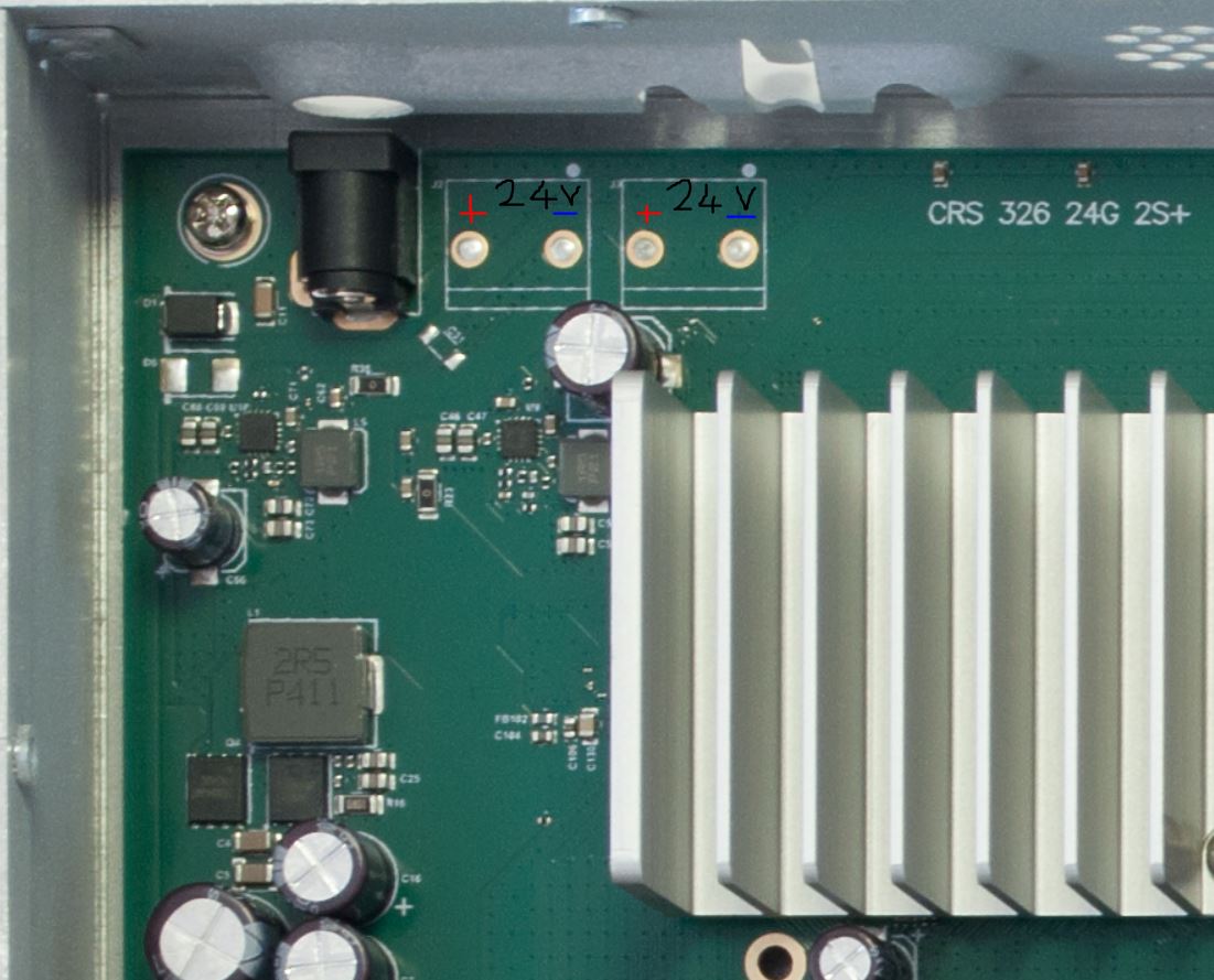
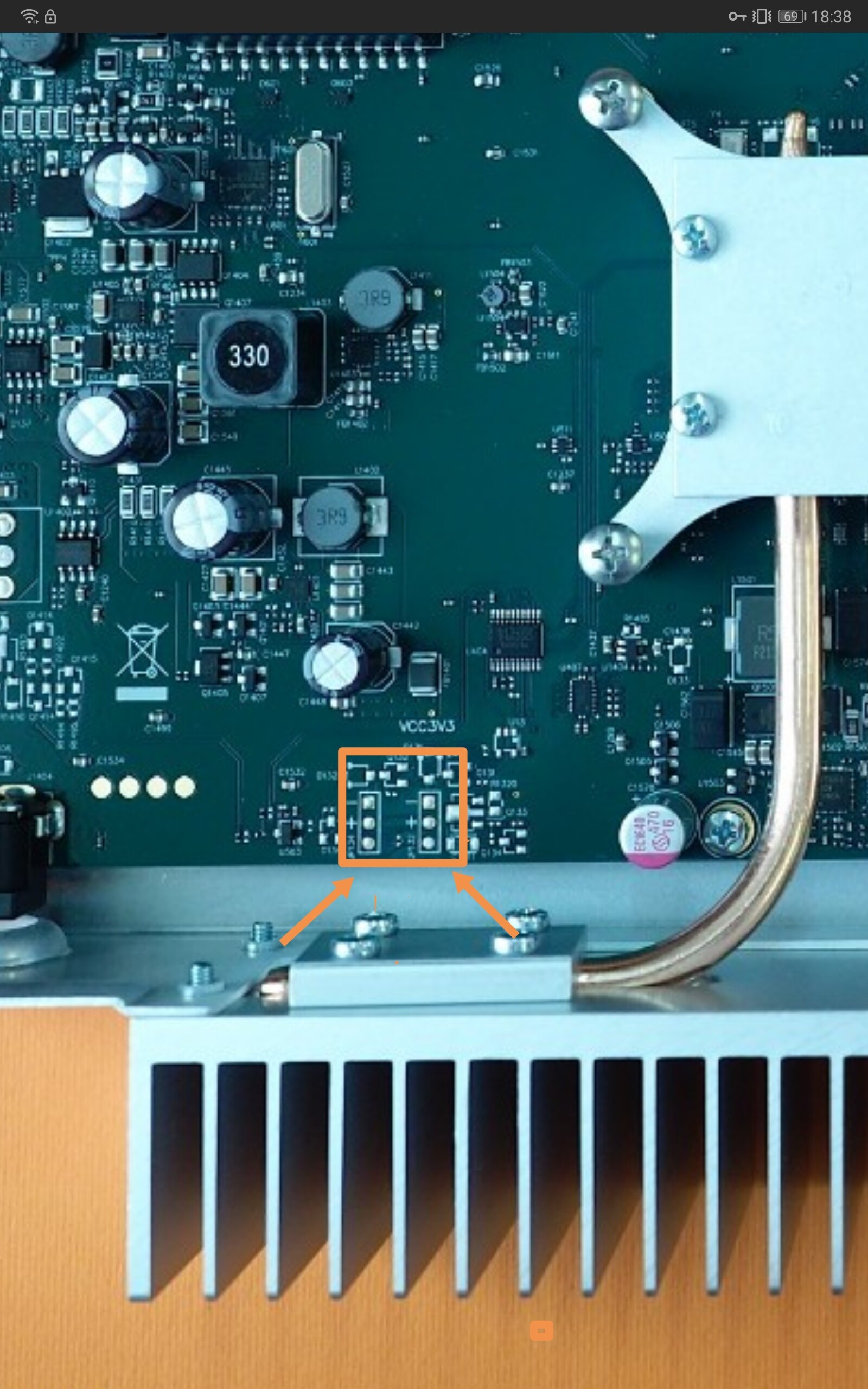
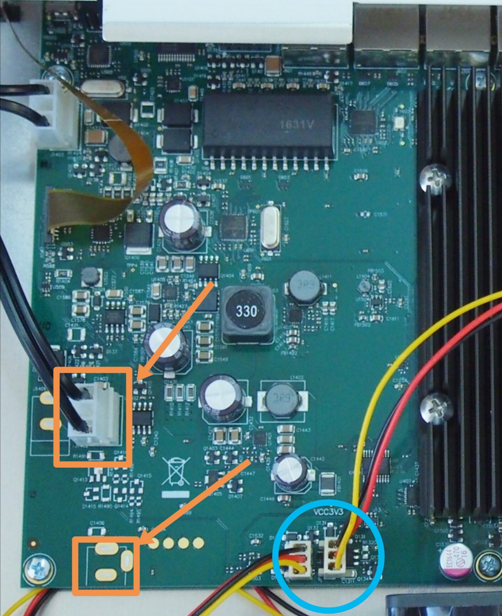
That are two+two soldering points for extra power inputs. The plus is the one closest to the connector and you see the resistor which connrcts to the plus.
If you are not comfortable with soldering look at a splitter cable to be fitted in between the power cable and the power in connector. The fan comes with resitors cables.
The rj01 is known for his heat and there a different heatsinks that have bigger ribs.
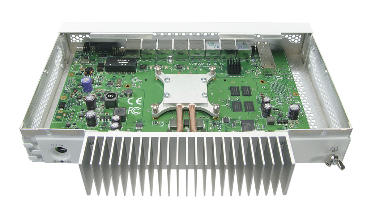
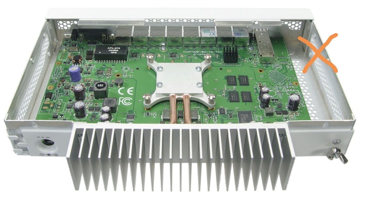
No NO, that looks like a stock picture of inside the CCR1009. It has those BIG copper pipes leading to the heat sink with large fins. THe fins get really hot, I think I could use them for cooking LOL.
That are two+two soldering points for extra power inputs. The plus is the one closest to the connector and you see the resistor which connrcts to the plus.
If you are not comfortable with soldering look at a splitter cable to be fitted in between the power cable and the power in connector. The fan comes with resitors cables.
OK, I think I see that, although the image is a little unclear. Could you confirm I have understood you correctly by taking a look at the image below? You say that each of those is a 24V outlet and the positive is on the left in each case? What is the max. current for each of these? If you don’t use a resistor would you just solder the cable directly to those points?
I am wondering now whether it might be easier (i.e. less physical modification to the board) to fit an internal PDU and power the fan directly from that, either with a splitter or using a twin output PDU, in combination with a step down DC-DC buck converter in line to the fan.
Ah, thought it was your image. Apparently the copper pipes work very well and the so-called “heat pipes” even better. Having seen this, I’m wondering whether just to add additional passive cooling with copper pipes and an external heat sink to my CRS-326.
I’ve just received my 12V Noctua FLX fan.
I just powered it from a 18V supply with 330ohm resistance in series with the positive line.
This is what I measured on the connection of the fan during power up.
As you can see there is no voltage spike above the 10.8 Volt. On average the voltage on the fan was about 7.5 Volt.
I’m confident that you can use this fan with a dropper resistor if needed
(I will use it to lower my RPM’s, if the airflow is not enough I can take the resistor out, as I will power my switch with an internal 12V supply).
If you are looking for the fan soldering pads and looked at the bigger versions of the 1009 which share the same boards. Just looking at pictures on the internet.
There are no components around those pad so likely also no power on the pads.
I would advise a power source coming from the outside. You can stick the fan on with little pieces of doublesided sticky tape.
If you look at the holes in the housing the flow of heat is mainly to the front. The heat of the processor is transfered to the heat sink at the back.
Why 3 wires? I see a + and - on the previous diagram what is the third soldered spot for, closest to the back of the chassis??
I suppose one could check if they are powered by hooking up a multimeter? I wonder if that capacitor close by (11 oclock)is affiliated or not…
It could be that the power is present and that the components are there to interpreted the rotating speed. But then if you seek 12V then those two of three pads is a good try.
Okay but looking at fans, I see we can get USB fans but what is ideal…
This looks Really promising,
Roughly 6 inches wide, 2.4 inches high and 1.5 inches deep
could the USB port on the MT run the fan LOL??
both require 5V, this is not noted on MT unit
One fan requires .7A, the other 1A, seeing as the MT puts out 1A, the first one is more likely to work??