Has anyone done this? Do MT supply fans for the CRS-326? Most MT devices run quite hot and with the MT RJ01 10G interfaces I would prefer to have a fan running in this. Currently the SFP interfaces are at 87 degrees C. I notice the switch is prepared with a fan vent on the body.
Any pointers would be appreciated.
Using search delivered a starting point: http://forum.mikrotik.com/t/css326-24g-2s-active-cooling/109406/10
That’s useful, thanks.
Any other experiences with this modification to the CRS-326 would be useful to have.
http://forum.mikrotik.com/t/adding-a-cooling-fan-to-crs326/138630/1
At the moment my CPU is at 69-70 degrees with an ambient temp of 21 degrees.
I’m planning to also install a fan in my CRS-326. Probably a Noctua FLX fan that I will reduce in speed by adding some resistors in series with the power supply.
I might even install a small switch on the front of the router to switch between high/low RPM’s.
While I’m at is I’ll also install an internal (12V/36W) power supply.
https://www.instructables.com/Mod-Internal-Powersupply-Into-Mikrotik-CSS326-24G-/
And some heatsinks on the SFP cages.
http://forum.mikrotik.com/t/sfp-module-is-extremely-hot/117746/1
This way I hopefully only need to open and service it just once in his lifetime..
Thanks for the info @mvdswaluw . I’m having trouble sourcing a fan. There are so many out there that I don’t know which would be best on quality and some are supplied without connectors. I found Noctuas but could not find any at 24V. Is your Noctua 24V? Can you use a 12V fan on that board using the free J2 connector? If a fan is supplied without a connector, are they easy to fit? I don’t have many tools and if I have to buy these just to fit a connector (I probably won’t use the tools again) the price of the switch begins to rise. Not sure how easy it is to fit the connectors.
It’s a shame that with the fan connected to the board it doesn’t run if the switch is supplied via PoE. I suppose there is no way round that?
I’ll add a few resistors in line with the power connection of the fan to drop the voltage. See this https://www.youtube.com/watch?v=vjL38udVS24 link why.
I have three 1 Watt resistors that I will use so they won’t get as hot as in the clip. Also I will mount them somewhere in the airflow.
Do you realise that the Noctua FLX fans usually come with a speed-reducing adapter cable (with a built in resistor that’s just right)?
You certainly don’t need multiple 1W resistors, at least if you are powering the fan from that 12V PSU you mentioned. I would not power a 12V fan from 24V even with dropping resistors because the fans draw current in pulses so would most likely experience overvoltage anyway.
I’ve just made myself a PiHole box inside a recycled old switch case, with two Raspberry Pi running PiHole, powered from the 12V PSU that was in the switch. Two Noctua fans in it are controlled by a Tasmota programmed 4-channel relay card so I can switch them off/low-speed/full-speed by remote or let the Pi control them from its own temperature monitor.
As soon as another Noctua arrives (this week) I’m adding it, with a PWM controller this time, and a PSU to my RB3011.
I didn’t know that. So do you think that I will be able to fit a Noctua FLX directly to the 24V board with this reduction cable? I would rather not add a DC-DC step down box as well as the fan because it just adds unnecessary complexity and another point of failure.
I have seen several comments on various forums about the quality of Noctua but unavailability for 24v boards.
If you think the speed step down cable supplied with the fan means I can fit it directly to the free J2 on the CRS-326 board then I might try it. But for me speed reduction is not necessarily voltage reduction - although it may well work.
Thanks.
I put those mini heat sinks on all my SFP to copper cage locations, seems to work well.
The CCR1009 does get very hot and have toyed with the idea of a fan for that but too chicken to try it.
![]()
Which mini heat sinks are they? Could you send a reference?
No, that’s not what I said. It’s for 12V only. You said in your previous post you were going to add a 12V power supply; that will run the fan. I would not connect a 12V fan to 24V even with a resistor - see my previous post for why. You might get away with it and the fan will survive, but I would not do it myself.
Perhaps I misunderstood your intent, with the 12V PSU.
Perhaps I misunderstood your intent, with the 12V PSU.
Personally I will install a 12V 35Watt supply and install resistors to limit the RPM’s of the fan.
In my opinion there is no need to run a fan at 100% speed if the CPU temps ar OK at a lower speed.
Running at 100% will only generate more noise and wear down the fan faster Also accumulation of dust will be reduced with less airflow.
The fan is in backorder. Once received I will measure the voltage with an oscilloscope to see if you are right with your hypothese that the voltages will still spike. I doubt it, but I’ll check.
Sure,
https://www.amazon.ca/gp/product/B07Q8RW5Y2/ref=ppx_yo_dt_b_asin_title_o00_s00?ie=UTF8&psc=1 (this is what I got)
Similar
https://www.amazon.com/Raspberry-Heatsink-Conductive-Adhesive-Aluminum/dp/B07YR6M6F6/ref=sr_1_13?dchild=1&keywords=Heatsink+kit&qid=1613575672&sr=8-13
https://www.amazon.com/Raspberry-Heatsink-Conductive-Adhesive-Aluminum/dp/B082RWXFR2/ref=sr_1_4?dchild=1&keywords=Heatsink+kit&qid=1613575642&sr=8-4
I would be interested to see. I disposed of most of my electronics kit, DSOs included, a year back when I decided I no longer needed it all.
TI have already done this though. Take a look at this app note which shows some current graphs for BLDC fans: https://e2e.ti.com/cfs-file/__key/communityserver-discussions-components-files/196/TPS2592AA_2D00_APP-NOTE_2D00_DC-BRUSHLESS-SAFE-START-UP.pdf
Even at startup, the current drawn by the fan ramps up, so the voltage across the dropping resistor will be low at first. I.e. the voltage across the fan will be high. BLDC fans are not linear loads. Like I said, you might well get away with a resistor and the fan will survive (we are only talking low voltages/currents after all) but I would rather not have to replace an expensive fan early because of it. (Noctua fans are expensive to me, although I rarely buy anything else.)
The confusion is because the 12V PSU installation was somebody else’s post in this thread, not mine. I just intend to add cooling at the moment. Adding internal PSUs is far too advanced for me.
Great, thanks. I’m in Spain so will see if I can source these or something similar. Amazon is different in each country. I couldn’t find the one’s referenced in early posts or other threads. I don’t want to buy junk, as sometimes happens with Amazon.
OK, thanks anav.
OK, so before going ahead and ordering cooling equipment I was taking a look at the board for the CRS326-24G using the high res image on the MT website. I cannot see where the connector for the fan is. Can anyone mark it for me on here? From a previous post I had understood that the board was ready to add a fan with a 3-pin connector.
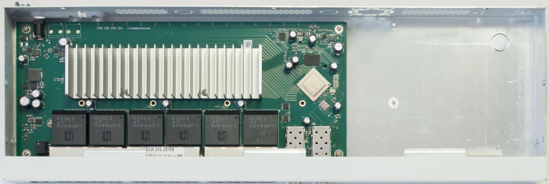
Do you remember my posting? It’s shown in the pictures of that topic.
Two pins, plus and minus.