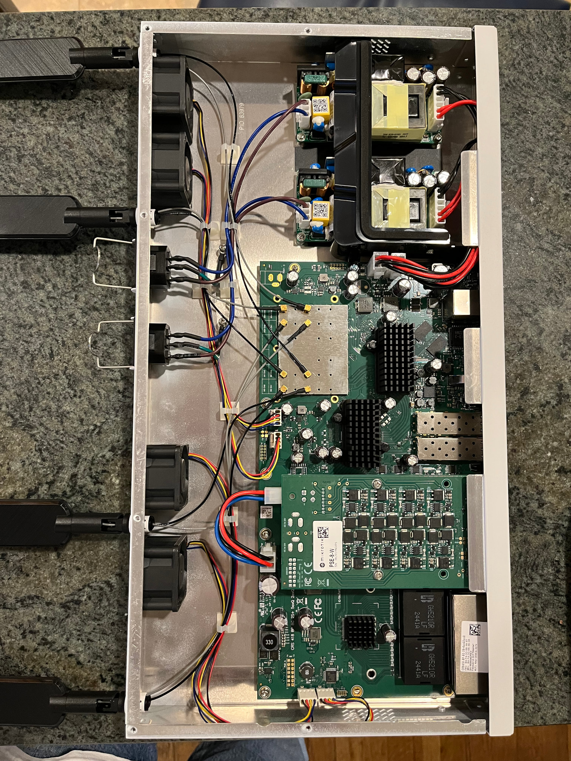
Just purchased a CRS418-8P-8G-2S+5axQ2axQ-RM with the intention of putting it in a road case for events, trade shows , etc. Seems like a perfect use case. Unfortunately the antennas are not removable and don’t work on the back. My intention is to add SMA connectors as described in the brochure but there seems no documentation. Inside the unit there are 8 UFL connectors (4) for 2.4 GHz and (4) for 5 GHz but only (4) spaces in the case to accept SMA connectors. How is this supposed to work? The permanent antennas have 2 pigtails. One connects to 2.4 & one to 5 but I don’t believe there is any way to do this with an SMA connector. Do I need 8 antennas? Any Ideas?
Hi,
Where do you want to move antennas? To front? Up?
A little of drilling would be needed to pass cables but consider printing in 3D new holders/clamps to be installed at the place you want and move old antennas there.
Ideally I’d like to put the antennas in a blank panel above the router. Of course I can drill some more holes but the unit is supposedly prepped for what I want to do. Install SMA dongles with SMA antennas. However, 4 holes doesn’t make sense if you need 8. Trying to figure out what I’m missing…

Maybe you can use dual external antenna sets to move them outside rack.
Cables can bu passed through existing holes after dismounting current antennas.
Yes, there are 4 pre-punched holes. Does that mean I will need 8 antennas once I go external? 4 2.4GHz & 4 5 GHz? I haven’t been able to find any documentation on this feature.
That’s interesting - I guess I would need four of them.
Well, you have 8 UFL connectors, so if you have antennas with 2 wires (like the factory ones) you need 4, if you have "normal antennas" with 1 wire, you will need 8 of them.
I presume that the original idea (hence the pre-punched holes) is to install 8 SMA panel connectors with pigtails, using the 4 existing holes replacing the antennas and the other 4 pre-punched ones.
Also using dual antennas (like the one Bartoszp suggested) you will need 8 SMA connectors (and 8 holes).
There are also rackmount accessories, but it depends on the kind of rack you have, example only:
https://racknex.com/antenna-rackmount-kit-nm-ant-002/
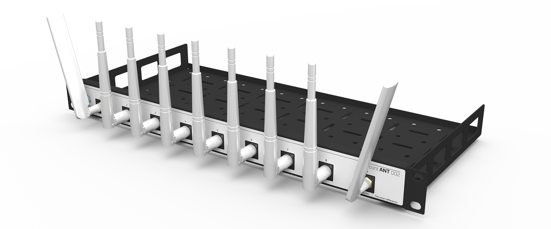
Yes, very helpful! My intention was to fabricate something similar with a 1RU blank panel. 8 antennas was more than I was hoping for but sounds like the correct approach.
For me the idea of rack device with antennas at the back is .... let's say strange 
How on earth it is expected to deliver good signal from inside the Faraday's cage?
How to set antennas strigth up/down if there is another device installed above or below? Or set of cables from RJ45 panel?
External single or dual antennas let to install them outside the rack to get the better signal levels than from inside.
It would be my choice.
 .
.
I was planning on using this exact switch and was hoping to simply extend existing antennas 18”-24” to the outside of small wall mount rack.
Looks like they can’t be reused and I will need 8 new antennas and U.FL to RP-SMA pigtails?
Does Mikrotik makes antennas for them?
Usbuild, very similar to my plan. I was expecting to use 4 antennas & 4 pigtails but it appears 8 are necessary. None of this seems documented by Mikrotik. So far I haven’t come across specific Mikrotik pigtails or antennas available but there appear plenty of generic options.
Totally agree with BartoszP! I see many use cases for this device but the rear mount antennas make no sense. The designer clearly has never attempted installing in a rack! If I can find enough real estate on the front panel, I may try drilling (4) holes and relocating the factory antennas to the front.
so it’s another $60-100 on top for antennas plus 2 hours labor and you end up with questionable/untested setup.
Might as well get crs328-24p plus cap ax and call it a day.
It looks like the standard antennas are “dual-band” (2 and 5 GHz) with 2 cables for the 2 bands.
When you can get similar antennas you can use 4 of those, but you still have 8 cables… so it doesn’t matter too much for the problem at hand.
When you remove an existing antenna, is the hole suitable for SMA?
Anyway, no matter how you do this it will always be a compromise solution for WiFi. It will always be better to use the non-WiFi model and then add WiFi accesspoints in the location where you need them.
Maybe WiFi in the serverroom is nice as well, but why have 4 antennas for that…
I appreciate all the comments about this not being ideal but the form factor is the advantage in this use case, think portable setup, trade shows, small events, office trailers, etc. Installing it in a road case, think musicians, makes deployment a breeze, durable, easy to ship, plug & play. We drop the case on the table, plug in the internet (fiber or Starlink) add some IP phones & were off to the races. We do add additional AP when necessary, managed by Capsman, but for small setups where one is plenty, an AP in the case is great.
Maybe you can use a sturdy plastic case?
Otherwise, you could relocate the two rightmost antennas to the front, that should be doable. You can then disable 2 of the 4 chains.
@kerensen
So, a special kind of "travel router"?
Something loosely similar to this one (example only), right?:
https://buypeplink.com/product/sfc-hd4-mbx-5g-40g-3u-1b/
Yeah it’s a shame they didn’t put rack mount holes on the back in addition to the front. That would allow you to at least mount it backwards, plug all the gear in the back and have the antennas hang out the front of the road case. Also a shame the antennas aren’t easily removable.
I have a 4011 rack-mounted in a small 4RU open rack for this same purpose, and the antennas are flat pointing backwards, but since it’s open, it works well.
I would think mounting it in the top of one of those rugged plastic cases would work too.
What is the depth of that thing with antennas laying flat? 6.5” roughly (156mm) plus another 6-8” (150-200mm)?