It depends. If you have for example separate network for guests, one way to isolate it can be firewall on AP. But I’d rather choose VLAN, do all filtering on router and keep APs transparent.
Rules to live by For Accredited Trainers:
From MTUNA Appendix, Things they dont teach you at MT School.
As soon as one has multiple subnets hitting the AP, a smart donkey would move towards vlans, a dumb ass would keep trying to shove spaghetti up a straw!
Analogous in a way is the other rule to live by
From MTUNA Appendix, Helping others on the forum
Don’t be too soft, RIP OFF that bandage, its actually much more painful to remove it slowly!
For now there are 3 segments and 3 SSID in the wireless AP.
In the fw chain there are about 25 rules in the AP, to allow/deny traffic between segment.
All are using the default gw to the main router, and there are static routes in the main router, so no double NAT.
-When extending to 5 or 7 AP i want a solution with no fw rules in the AP, and only in the main router.
But how to do that?
Well, listen to the wise ass, rip it off. Convert your three segments into three VLANs on main router, and then connect as many APs as you want with only minimal config required to put users in VLANs. Everything else will be done on router. If you want more detailed instructions, provide more info, what exactly you want from those three segments, what’s your current config, etc. And the friendly flaming animal will tell you how to change your router so well that you won’t recognize it (but you may actually like the result).
If making VLAN will you the use the trunk port to connect to the AP, If not i cant understand it?
What will it change if using VLAN according to the 3 segment, the ip must be routed…?
Maybe give an overview so i get what you mean:-)
That’s three separate networks (VLANs 10, 20, 30), with fourth for administration (VLAN 100). AP itself is part of only one network (admin), so it doesn’t even try to route anything between others. Everything in those other networks (DHCP, inter-VLAN routing, firewall) happens on main router.
What Sob missed out on was directing you to the standard for setting up vlans
There is an example there just for Access Points, post #4.
What I suggest you do is start at the beginning and digest the information and then go back and forth from the explanation and Post #4 to come to grips with the config setup. http://forum.mikrotik.com/t/using-routeros-to-vlan-your-network/126489/1
The key points are
one bridge
All subnets described/identified as vlans and with parent interface being the bridge.
No firewall rules
Only one interface list entry called MANAGE or BASE
The trusted vlan is usually the only interface as a list member (you dont need a separate vlan for management purposes if you the admin actually reside and exist on an existing trusted vlan like home (not guest or iot devices etc…).
What is important is that the AP gets an IP address on the trusted vlan subnet.
The interface list is used in three places typically, a. neighbours discovery setting and b. tools/winmac server
One IP route required and its typically dst-address= 0.0.0.0/0 gw=gatewayIPof trustedvlan table=main
However, its really tricky setting up the bridge when changing subnets and settings within the bridge.
Two recommendations
Thank you both:-)
You have pointed me in the right direction.
I actually have an extra router, and some AP.
Now I will try to set it up, and test in a closed environment.
I will return for sure when I hit a wall.
My main router is connected to the big www. It also handle 192.168.10.0/24 for DHCP and DNS. It will be connected to the MT router in the untagged port 1.
On the MT router normally the WAN port is served with a DHCP client.
In my case it will be assigned a static ip as 192.168.10.4/24 and have a DHCP relay because the DHCP assignment for that segment is coming from the main router.
I still need a VLAN_10 to handout ip on the AP with ip from my main router.
Port 1 is static ip 192.168.10.4 connected to my main router.
Port 2 VLAN_10 and the same segment as the port 1 but DHCP is from the main router.
Port 3 VLAN_20 DHCP is from the MT router
Port 4 VLAN_30 DHCP is from the MT router
Port 5 Trunk port with VLAN_10, VLAN_20, VLAN_30.
The complicated thing is the MT router must have a VLAN_10 there are the same segment as the port 1
Any particular reason for requirement of having same subnet on two interfaces (ether1 and vlan_10)? It is possible to have it, but configuration for that is convoluted.
I dont follow, it seems you have a modem router that you have no control over?
Most allow you to port forward any ports required!
Suggesting, just use the one LANIP from the main router, which is also the WANIP on the MT router as the one conduit to the MT Router.
Then you can do whatever you want on the MT router. All traffic will go out the WAN port of the MT router and through the main router to the internet???
I am not understanding the requirement for the additional complexity??
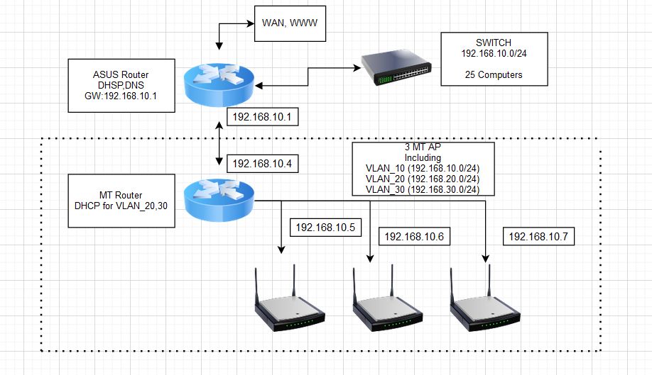
This simple drawing show what i want.
It is only a drawing not a real network layout.
The 192.168.10.0 is the main segment and the DHCP i in ASUS.
The MT must connect to ASUS and have the VLAN 10,20,30. VLAN_10 is the same segment as in ASUS, and all client get ip from ASUS.
The MT do all the rest VLAN_20,30.
The Trunk from MT is to my MT AP, and other switch.
So the switch connected to the Asus, is a dumb switch?
Any reason why you cannot connect the switch to the MT router instead?
Is the asus vlan aware?
In terms of dhcp you want
the asus to hand out DHCP for vlan10
the mt to hand out DHCP for vlan20,30
the mt to handle Firewall rules for all three vlans…
The switch is just a normal networks switch. It just serve as illustration for the 25 client, some are connected with other switch.
Main reason for MT router is to get WIFI in all places, and segmentation for some users. For now we want the ASUS as the main router for 192.168.10.0/24. And therefore the MT must handout WIFI addresses for that segment too, DHCP 192.168.10.0 came from ASUS.
The simplest way of achieving what you want is to use mikrotik as a bridge (switch) main segment / vlan_10 and only act as router for the rest of vlans … you would achieve that by configuring port1 as access port for vlan_10, other porrs as trunk ports for all vlans (or access ports for select vlan, depending on how they are used). Bridge interface is tagged member of all VLANs, you need vlan interfaces for all VLANs. Etc.
For now the MT router is up and running as expected.
One more time thanks for all the hints, and help
But…
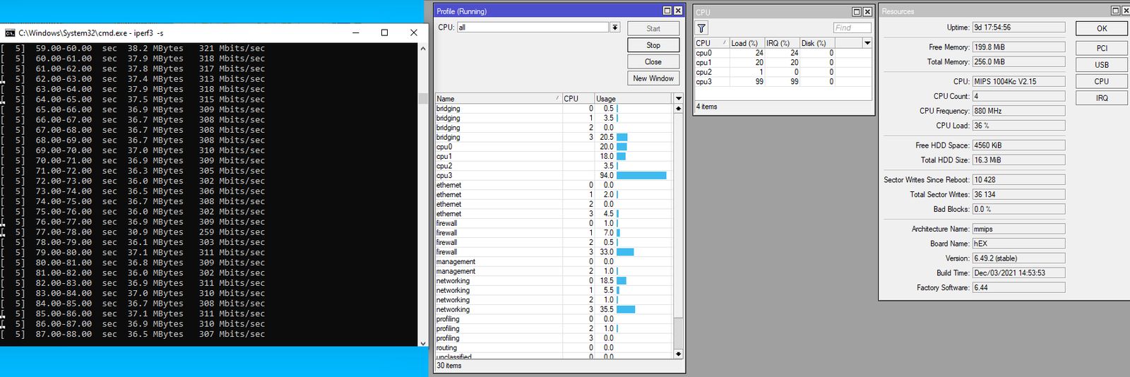
Is it normal that speed between two VLAN is about 310-350Mbit, and CPU load about 99% at one core (RB750Gr3).
Test is done in mimimal setup, no fw roules. Test is with cat6 cable, directly from MT to two computers.
When testing on same bridge without VLAN, speed is about 750Mbit, and CPU load is low.
Update: When doing more streams 3-8 are tested at VLAN, speed is about 700-750Mb between segments, so for me ok . And then it spread it over more CPU.
This is what i cooked, for now:
# jan/07/2022 11:10:40 by RouterOS 6.49.2
#
# model = RB750Gr3
/interface ethernet
set [ find default-name=ether1 ] comment="vlan_10 and to main router"
set [ find default-name=ether2 ] comment=vlan_10
set [ find default-name=ether3 ] comment=vlan_20
set [ find default-name=ether4 ] comment=vlan_30
set [ find default-name=ether5 ] comment=trunk
/interface bridge
add name=bridge_vlan vlan-filtering=yes
/interface vlan
add interface=bridge_vlan name=vlan10 vlan-id=10
add interface=bridge_vlan name=vlan20 vlan-id=20
add interface=bridge_vlan name=vlan30 vlan-id=30
/interface list
add name=LAN
add name=BASE
/ip pool
add name=dhcp_pool_20 ranges=192.168.21.100-192.168.21.149
add name=dhcp_pool_30 ranges=192.168.30.100-192.168.30.149
/ip dhcp-server
add address-pool=dhcp_pool_20 disabled=no interface=vlan20 name=dhcp20
add address-pool=dhcp_pool_30 disabled=no interface=vlan30 name=dhcp30
/interface bridge port
add bridge=bridge_vlan frame-types=admit-only-untagged-and-priority-tagged \
    interface=ether2 pvid=10
add bridge=bridge_vlan frame-types=admit-only-untagged-and-priority-tagged \
    interface=ether3 pvid=20
add bridge=bridge_vlan frame-types=admit-only-untagged-and-priority-tagged \
    interface=ether4 pvid=30
add bridge=bridge_vlan frame-types=admit-only-vlan-tagged interface=ether5
add bridge=bridge_vlan frame-types=admit-only-untagged-and-priority-tagged \
    interface=ether1 pvid=10
/ip neighbor discovery-settings
set discover-interface-list=BASE
/interface bridge vlan
add bridge=bridge_vlan tagged=ether5,bridge_vlan untagged=ether2,ether1 \
    vlan-ids=10
add bridge=bridge_vlan tagged=ether5,bridge_vlan untagged=ether3 vlan-ids=20
add bridge=bridge_vlan tagged=ether5,bridge_vlan untagged=ether4 vlan-ids=30
/interface list member
add interface=vlan10 list=LAN
add interface=vlan20 list=LAN
add interface=vlan30 list=LAN
add interface=vlan10 list=BASE
/ip address
add address=192.168.21.1/24 interface=vlan20 network=192.168.21.0
add address=192.168.30.1/24 interface=vlan30 network=192.168.30.0
add address=192.168.10.4/24 interface=vlan10 network=192.168.10.0
/ip dhcp-relay
add dhcp-server=192.168.10.1 disabled=no interface=vlan10 name=Relay_ASUS
/ip dhcp-server network
add address=192.168.21.0/24 dns-server=192.168.21.1 gateway=192.168.21.1
add address=192.168.30.0/24 dns-server=192.168.30.1 gateway=192.168.30.1
/ip dns
set allow-remote-requests=yes servers=192.168.10.1
/ip firewall nat
add action=masquerade chain=srcnat ipsec-policy=out,none out-interface-list=\
    BASE
 ###masquerade will be replaced later by static route in ASUS...
/ip route
add distance=1 gateway=192.168.10.1