I’m trying to understand VLAN routing in Mikrotik, some docs like Bridge VLAN Table helped a lot, but I’m still lacking a core understanding of where packets go and how they are routed inside a Mikrotik router. Is this explained somewhere?
I tried to draw this:
/interface bridge add name=bridge
/interface bridge port
add bridge=bridge interface=ether1
add bridge=bridge interface=ether2 pvid=99
/interface bridge vlan
add bridge=bridge tagged=ether1 untagged=ether2 vlan-ids=99
/interface vlan add interface=bridge name=VLAN99 vlan-id=99
/ip address=192.168.99.2/24 interface=VLAN99
# Forgot that in v1 of this post
/interface bridge set bridge1 vlan-filtering=yes
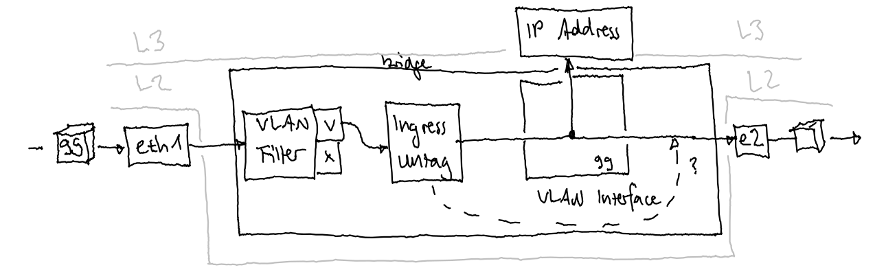
which most likely does not look like that: (Sorry for the wiggly lines, the drawing is actually quite small, but looks terrible on large screens)
So, I’m wondering …
How do I know the order in which the different filters apply?
How and where are different interfaces (physical interface, bridge interface, VLAN interface, …) connected?
Is the Bridge VLAN table applying at multiple locations, e.g. if I add untagged=bridge, will it filter packets both after entering ether1 and after entering bridge?
Will the VLAN interface receive tagged packages or untagged ones because the tag has already been removed?
I know these are really basic questions, but I could not find any answers to them. The Internet provides a lot of “that’s how you do it”, but not the why.
IMO the best MikroTik page on topic is Packet Flow in RouterOS - in particular the “Flow of Routed Packet” section.
It’s opaque reading at first but helps understanding other pages which help understanding flow - a virtuous or vicious circle - take your pick.
in basic terms, vlans are a conveniently way of packaging subnets since it conveniently isolates subnets from each other at layer2 (mac address).
So in a way it does accomplish removing packets/traffic between subnets.
However a router looks at connecting users/devices at layer 3 (IP address) and thus we need to ensure through filter rules (firewall rules), to prevent that from occurring.
There are different ways to accomplish the same thing. The MT default setup basically states stop a few known bad things and let the rest of the traffic happen.
Great for a newbie connecting initially. However better, once comfortable to config, is to change the concept or approach to allow known desired traffic and drop everything else.
In this way one doesnt have to know any of the bad traffic as its dropped if not desired.
However, traffic cannot actually get anywhere without routing
Filter rules - is it allowed
Routing - is there a path
the router automatically creates default routes for any interface with an IP address
seen in Route Prints with .
the router creates routes for WAN connections if the admin has selected the checkbox for Routes
the admin can create manual routes for anything else required.
Unfortunately the Mikrotik packet flow docs are not just exhaustive, they are also overly complicated so don’t worry if you don’t get the principle at a first try. It’s actually much easier than you think once you’ve found the red thread.
Since RoS is based on Linux you might get more comprehensible explanations if you google “iptables”. The only differens is that RoS execute iptables instructions in the background using tools like Winbox. Another thing you should be aware of which might be very confusing at first is that Winbox mixes “input” and “forward” in the same window but are in real life completely separate chains.
Next is find your devices respective switch chip model (if any) here: Switch Chip Features
The lower table maps RouterBoard model to the respective switch chip. The upper table enumerates switch chip features.
I suggest bringing reading questions here; I’ll do what I can. Be safe and best wishes.
In addition to Larsa’s input
the input chain can be thought of as traffic to the router LAN to router, WAN to router.
the forward chain can be thought of as traffic through the router LAN to WAN LAN to LAN WAN to LAN
In your diagram the “VLAN interface” box should be outside of the bridge, and the bridge interface is where the L3 VLAN interfaces meet the bridge – not inside it. But it more like a Venn diagram: check out the “RouterOS bridge mysteries explained”: http://forum.mikrotik.com/t/routeros-bridge-mysteries-explained/147832/1
Basically the VLAN table in the bridge is essentially the allow/deny at the L2 layer, which is entirely separate from VLAN interfaces that are L3 constructs.
Ammo, that was the best comment on vlans for me! You must be getting water in CA these days, the brain is no longer just pickled from mexican beer.
Serioiusly, that was a nice way of splitting things up…
I liked the diagram OP had – it’s actually useful way to look at it – just the boxes were wrong.
BUT now that I look at the config OP has…that’s also wrong. It doesn’t show vlan-filtering=yes – I kinda assumed that part since he references @pcunite’s VLAN manifesto…
So without vlan-filtering=yes, the bridge is an “unmanaged switch”, thus all ports become"trunk ports". VLAN 99 still be there, on all bridge port members, based on /interface/vlan listening on the bridge interface. BUT the pvid= and /interface/bridge/vlan stuff is ignored without vlan-filtering being enabled. Now if vlan-filtering=yes is added to the snippet, then ether2 would would be an “access port” to the VLAN interface with subnet of 192.168.99.0/24 on it – based on the pvid=99 being set. But since the default is for ingress-filtering to be off, the /interface/bridge/vlan stuff in snippet does nothing.
So if the expectation is that VLAN 99 is untagged on ether2, that’s not what this config does:
NO need for vlan filtering if vlans are associated directly to etherports and not the bridge.
Another reason why once you start using vlans, I prefer vlans for all subnets and have the bridge do no DHCP.
Clear, consistent approach.
Thanks for all your answers! I see some things more clearly now, especially the routing part, and others have become more misterious
First, I forgot to enable vlan-filtering in my initial post. It should be vlan-filtering=yes.
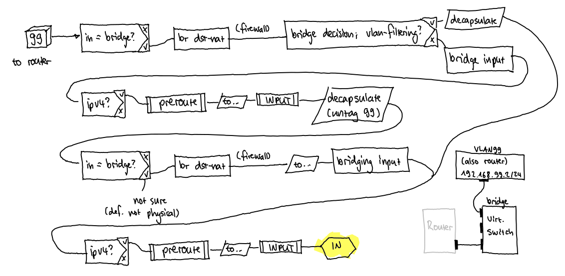
After going through the packet filtering docs, I imagine the package would be routed as in the following picture. With VLAN filtering enabled, it would end up quite quickly on LOCAL_IN because it is already decapsulated in the first bridging decision visit and not after visiting the L3 routing decision. Without the VLAN filter table, it would do an additional round trip through the whole chain. (Please correct me where I’m wrong.)
What does not fit into this picture yet is the VLAN interface. The drawing on the bottom right is my current understanding of what this configuration would look like according to the “RouterOS bridge mysteries explained” forum post. The /interface/vlan would create an additional (L3) interface connected to one of the ports of the virtual switch (i.e. the /interface/bridge I created). But how does the VLAN come into play here? Isn’t the VLAN interface already the LOCAL_IN where the packet has long ago been decapsulated from the VLAN tag?
When physical in-interface receives VLAN-tagged frame, it passes the bridging magic (which determines it’s destined to router itself … so passing points A and B), then passes all those diamonds via “NO” branch until reaching diamond “Decapsulate?” (yes, it passes “IPv4?” via “NO” branch, because outer header says that frame is ethertype 0x8100 “VLAN 802.1Q”). It exits this diamond via “YES” branch, hitting parallelogram “DECAPSULATION” which strips off the VLAN header. And that’s the function of “/interface vlan” interface. Then packets returns to the “In-interface bridge port?” diamond which this time exits via “NO” branch (because /interface vlan is not a bridge port) and proceeds to the right until “IPv4 traffic” diamond. This time it hits “YES” branch because the remaining ethernet header will say “0x0800 IPv4 packet”. Then this packet will enter routing jungle via point I. The jungle might include also the right-most grawed area (router processes), but it’s not important in this discussion.
On the way back out of IP routing jungle, packet will pass point L, then proceed using “NO” branch to the left until diamond “encapsulate?”. If it needs to be tagged on the physical out-interface, it takes branch “YES”, taking it right to the “encapsulation” parallelogram (this is the point where “/interface vlan” does the tagging). Resulting frame hits the “LOCAL OUT” hexagon, then proceeds via “NO” branches until it hits “ENCAPSULATE” diamond (again). This time, it follows the “NO” branch towards physical out interface.
The firewall INPUT and OUTPUT chains DO NOT APPLY to packets passing through the device (forwarding i.e. routing).
The firewall INPUT and OUTPUT chains apply to packets destined to or origination from router CPU processes.
Packets passing through device in SAME VLAN are bridged by switch and bypass CPU (firewall).
Packets passing through device in DIFFERENT VLAN are bridged according to VLAN Table by switch and bypass CPU (firewall) when “use-ip-firewall=no”.
Packets passing through device in DIFFERENT VLAN are bridged according to VLAN Table by switch and seen CPU (firewall) when “use-ip-firewall=yes”.
Packets passing through device and seen by CPU are subject to firewall PREROUTING, FORWARD, POSTROUTING chains.
Untagged packets entering physical interfaces (bridge ports) are encapsulated with the port’s “pvid=…” value.
VLAN encapsulation happens leaving CPU via virtual VLAN interfaces and leaving tagged physical interfaces.
VLAN decapsulation happens entering CPU via virtual VLAN interfaces and leaving untagged physical interfaces.
The CPU routes between virtual VLAN interfaces when “use-ip-firewall=yes”.
Physical interfaces excluded from bridge and assigned IP address can forward, input, output, and all are subject to routing tables and firewall.
Mixing physical interface routing and VLAN routing is overly complicated; using either method alone is the general recommendation.
Conceptually this is not true. Packets passing through device in different VLAN are routed and thus have to pass all the routing machinery. Unless L3HW is available and enabled this means CPU.
And even if L3HW is enabled, conceptually packets still pass the routing magic (even though it’s done in much different manner by switch ASIC).
I can’t say I’ve tested exhaustively but work with CRS326 suggests L3 Hardware Routing can bypass firewall per “use-ip-firewall” setting. At this level I’m expecting switch chip model variations.
I’m not sure L3HW helps understanding the conceptual mapping. In theory, L3HW should follow same configured IP routing, but yes the switch chip specifics would “superseed” the packet flow diagram WRT to firewall.
I think the part that’s potentially confusing is that from the bridge decision, inter-VLAN routing is an input, not forward, within the bridging decision box. This is how you get to the @mkx’s summary, in particular this one:
yes, it passes “IPv4?” via “NO” branch, because outer header says that frame is ethertype 0x8100 “VLAN 802.1Q”
which is how it comes “back around” to get to the routing decision (where it like be forward for traffic, except for local services like DHCP/DNS/etc. which are input in firewall).
But the docs do say which implies a “hidden untag” within the packet flow diagram:
Tagged packets might get decapsulated on the “BRIDGING DECISION” block, which means these packets will no longer match the mac-protocol=vlan and vlan-encap settings. Decapsulation can happen if the packet’s VLAN ID matches the outgoing port’s untagged VLAN membership
.
The critical thing to understand is VLANs are not bridge ports in the vlan-filtering=yes model - instead they are “slaves” of the bridge interface. So all the routing will still happen via the /interface/vlan - but how the ports and VLANs are wired in bridge is just plain confusing. And mainly because you have to be explicit about bridge being a tagged member in the bridge VLAN filing if you want Layer3 services on a VLAN.